Assembly lines in spaceEnabling construction of rotating space settlementsby John K. Strickland, Jr.
|
| Microgravity allows the assembly line to easily exist in three dimensions, so different surfaces of the structure can be built simultaneously. |
Before we had assembly lines, and standardized parts, all fabrication was done by hand and each item made, such as a Kentucky long rifle, was unique. The assembly line concept was established by Ransom Olds (for the Oldsmobile) in 1901 as a non-moving line, where the workers moved from one car to the next, doing the same task. The concept was quickly adopted by Henry Ford, who by 1913 had created the first moving assembly line where the vehicles being assembled moved past the workstations of the workers. This greatly accelerated the fabrication process. We now have very advanced assembly or production lines using rapidly moving robot arms to do most of the work. The robots initially operated by precise position, and now also with cameras and contact (touch) with the parts and object being assembled.
There are several areas where a space assembly line can and must be different from one on the Earth. Much larger objects such as power satellites or rotating space settlements would be in the process of being built, objects hundreds of meters or even more than a kilometer wide, whereas a transport vehicle such as a car or passenger plane is typically 5 to 50 meters long. Such large and massive objects with a mass comparable or larger than a fully loaded supertanker cannot be assembled on the surface and then launched into space. They must be built in space, in microgravity. Space habitats also would have multiple layers in their structure. Layers can be dealt with by assembling the innermost layers first, then the outer layers in sequence.
In addition, microgravity allows the assembly line to easily exist in three dimensions, so different surfaces of the structure can be built simultaneously. A good example is the pressure hull of a Stanford torus tube. The tube is the donut-shaped part—a torus. Since the pressurized inside of the circular tube, like a gigantic bicycle tire, would normally be more than 100 meters wide, assembly robots can operate both on the outside and the inside of the tube at the same time.
One of the basic principles of an assembly line is that the objects being built move past all of the assembly stations, while the components being used by the robots are brought to the assembly stations along a separate path. For an automotive assembly line, the workers and now the robot arms are positioned within a few feet of the conveyor system that moves the autos along. Robot arms do need to be mounted on some kind of fixed support structure to be able to move parts around and attach them in microgravity. Depending on the type of robot, the space assembly line robots might need to be further away from the working surface as they need room to move delivered parts and attach them to the structure. However, if the robots are stationed too far from the surface they are working on, or if the working surface moves too far away from the robots as it moves past, they would be unable to reach it.
So one of the basic principles of a space assembly line is shape conformity. That means that the object being assembled must move in a direction and be of a consistent shape so that the object’s surface stays about the same distance away from the robot arm’s stations as it moves past them. For a tube-shaped structure such as a torus tube, this implies a set of ring-shaped structure of work stations where the robots are mounted on surrounding the tube under construction. Another set of mounting rings can be inside the tube, to work on inner layers of the structure. Each such ring would consist of an open truss with the rail line on one side of it, probably the side facing the torus tube. The spacing of the ring trusses would all be the same so that with each step in the motion of the tube to the right, the same part of the tube would end up directly under the next ring truss with its robots doing the next sequential task.
With construction of such a torus tube, the entire tube must move since it is a single object. A torus tube 100 meters wide would be over 300 meters long. The torus tube would be moved in steps, stopping at intervals for each set or ring of work stations with their robots to work on it. As it is built, it would eventually emerge from the right end of the factory structure, slowly curving back on itself to form the giant donut shape. If the tube motion is (for example), to the right, the components would need to be delivered from the left side. Delivery of parts is a critical component of the assembly line. Ford’s Rouge Complex, built starting in 1917, had 145 kilometers of railroad tracks and nearly 200 kilometers of assembly line conveyors.
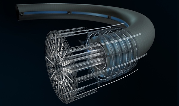
| For building a torus tube, the factory would need to curve to match the curve of the tube being built. |
An in-space supply system would use robot train cars, which would move to the right from the left end of a space factory complex past each ring of work stations. The robot arms could either use a circular track on each ring to get parts from the robot train, or a single mobile robot on each ring could supply parts to all of the robots on the same ring. All of this structure, needed to support precise positioning of the robots and to deliver the components, implies a rigid factory structure that is called a jig factory, since the entire factory is in effect a giant industrial jig. The in-space assembly line is thus a complex, three-dimensional structure with robot trains and robot arms all moving at the same time.
For building a torus tube, the factory would need to curve to match the curve of the tube being built. The work would be done in a hard vacuum, but the factory would have a hull to prevent constant thermal expansion and contraction as sunlight and shadow affected the components. The interior would be lit by lights powered by solar arrays, which would also power the robots and robot train cars. The hull would also have attachment locations for a hydraulic system to push the torus tube to the right at set intervals without interfering with the construction phases.
There would need to be a large docking area at the left end to accommodate a large number of tugs bringing components to the factory. Docking is a potential bottleneck since it must be done slowly. At this area, unloading robots would take the cargo and move it to robot train cars that would run on a longitudinal rail system: some lines running to rings inside the tube under construction, and others to rings on the outside. All rail lines would be mounted either on the inside surface of the factory or on individual open trusses inside the torus tube. The longitudinal rails would run within reach of the robots on the rails of the ring trusses, so there would be two sets of rails, one longitudinal and one on the sets of ring trusses. Depending on the traffic level on the longitudinal lines, there might be parallel return lines for empty cars. All of the robot cars would be held on the tracks with sets of bogie wheels similar to those used on roller coaster cars, so that the cars would not leave the tracks. The bogie system would also press the drive wheels against the rails to enable the cars to be propelled in microgravity.
If the tube under construction moves to the right, the ring trusses and work stations further left would have a larger diameter on the outside of the torus tube, and a smaller diameter on the inside. This order allows the “innermost” layers built by each ring of workstation robots to be built first, then the next and the next, with the outside of the tube getting wider as it is built, while each successive layer on the inside would be narrower.
In addition to the robots adding components at specific points on the tube, at certain places there would be robots adding layers of hull or decking. These would move some distance around the tube as the metal layers are added. They would still be mounted on the ring truss but some would be positioned over the middle of each hull or deck section to allow the attachment of new hull sections. Other robots would weld the hull sections to the previous section and also to the previous ring of hull sections to its right. The newest part of each layer (and the tube itself) is thus always to the left from this perspective.
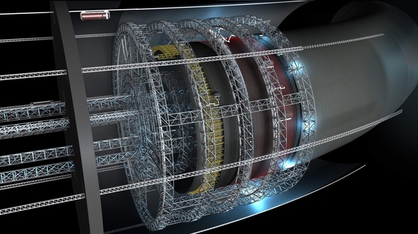 The jig factory: cutaway view of exterior ring trusses attaching hull layer materials. (credit: Anna Nesterova) |
In addition to these, there would probably be robots laying two sets or layers of cable similar to suspension bridge cables. These would run around a pressurized layer of the tube to hold in air pressure, or longitudinally around the circumference of the entire tube on the side furthest from the hub to hold the whole tube together against the rotational forces that would affect it once it was spun up. Which hull layers would need the cables and how many is an engineering decision.
Once the interior set of workstation rings was done with the top or innermost pressure hull, it would begin to create the set of deck levels below the top deck. This would require a ladder-like set of workstations in parallel lines. The last line of robot workstations would create the top or highest deck level, closest to the hub of the settlement.
As the robot system continued to add to the left end of the torus tube, the right end would curve back and get closer and closer to the docking deck of the jig factory itself. At some point, the factory would need to be disengaged from the main section of torus, and would then create a short section of torus that would need to be joined with the main section to complete the tube. Robots would need to work inside the two section to complete the attachment.
The other main sections of a rotating Stanford Torus are the spokes, the hub, the axle ends with the docking platforms, and sometimes solar arrays directly attached to the torus. Each of these would be created by a separate jig factory, with the factory’s geometry depending on the shape of each structure, which would then be attached to the torus.
| Using rocket-propelled robots to move and attach components would use a huge amount of propellant that would need to be replaced constantly, while robots on rails would use electrical power from free sunlight for movement. |
Due to the lack of friction in a microgravity and vacuum environment, the presence of small gravity gradient forces in any orbit makes floating objects slowly drift apart, even if touching others initially. Thus one of the main rules for a jig factory system in microgravity is that everything (inside or outside the factory), must be attached to something else unless it is in the process of being attached to something by a robot or is under propulsion with attitude control. For the same reason, any asteroid mine or smelter would need to be about 1,000 kilometers away from the jig factory set, so that loose material would not get inside the factory. It would make sense to have settlements created from materials from an asteroid to be in the same orbit as that asteroid (but thousands of kilometers away) from it, the smelter, and jig factory site to minimize propulsion needs.
The need for attachment and moving the very large and massive objects requires a connecting work structure, which I call a super-truss, at least several kilometers long and composed of second order trusses, where each truss component or strut is a truss itself. All of the jig factories would be attached to this huge truss. There would also need to be what can be called a super-arm and giant robotic hand, which could move along one side of the super-truss on rails and would be used to very slowly move the large components of the settlement to complete its assembly. The hand would not grip an object, but would use at least three attachment points on its giant fingers, (like the end effectors on the space station’s arm), to maintain control of the orientation of the object being moved by having three points of contact. The hand would use turret bearings as its finger knuckles.
There would also need to be a crew section at one end of the super-truss for human oversight of the whole operation and trouble shooting. The work crew could live in a small torus or set of radiation-shielded habitat cylinders.
Once final assembly of a settlement was completed at the super-truss site, it would be moved away at least 1,000 kilometers and then spun up. Finish work on the interior could then be easily completed, and more importantly, the jig factory set could immediately begin to build the components of the next settlement. Equipment and supplies for the finish work can be placed by the jig factory robots before spin-up or brought in later through the sets of docking ports.
Note that rotating settlements would be very difficult to expand, so the main way of expansion is to simply duplicate the settlement using the existing jig factory set. Each set is sized to create just one size of settlement, so for a larger settlement, a different, larger jig factory set would be needed. Making multiple settlements reduces the cost share of each set of factories per settlement.
Some have claimed that a structure like a jig factory is not needed to build rotating settlements. However, if the settlements are not built by robots, how then would they be built? Robot arms in space need to be attached to something to function at all. Using rocket-propelled robots to move and attach components would use a huge amount of propellant that would need to be replaced constantly, while robots on rails would use electrical power from free sunlight for movement. The sets of robots need to be attached to a common stiff structure so they can work together to create the components of a settlement. Whatever you want to call it, something like a jig factory is a necessity for many kinds of space construction.
Note: we are using a new commenting system, which may require you to create a new account.