EUROSPACE and the European spaceplane (part 2)by Hans Dolfing
|
| Yes, a payload fraction of 1%. Let that sink in. It shows why single stage to orbit has proven elusive so far. |
Figure 1 captures the 1963 Eurospace and Sänger dream of flying into space with a reusable spaceplane. In this particular example, it involves a system that would take off in a vertical manner (VTOHL). Many Eurospace Aerospace Transporter concepts were planned with a horizontal takeoff and landing (HTOHL) from conventional airfields to maintain flexibility of operations and target orbits. Before the individual concepts are discussed, here is one short engineering section to facilitate later comparisons.
Mass fractions
In Sänger’s ten-page paper titled “The Historical Background and Motivation for a European Aerospace Transporter Proposal”, he outlines in a very succinct way some back-of-the-envelope calculations and engineering parameters for an Aerospace Transporter concept. Basically, maximize the payload fraction fp to orbit. [1,2]
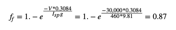
To illustrate, here is an outline which closely follows Sänger’s calculations. [2] In terms of the proportion of fuel mass or fuel fraction ff in a modern rocket propulsion system based on a specific impulse Isp of 460 seconds and an orbital mission with a typical characteristic velocity of 30,000 feet per second (9,144 meters per second) then the fuel fraction ff is calculated as:
 |
Therefore, with a structural, dry, or inert mass fraction of fs = 0.12 or 12%, the payload fraction is derived from the fuel fraction and structural mass fraction as
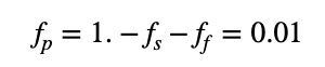 |
Yes, a payload fraction of 1%. Let that sink in. Such a mass fraction tuple (0.12, 0.87, 0.01) shows in a few numbers why single stage to orbit (SSTO) has proven elusive so far.
Sänger suggested several improvements to the payload fraction fp. For example, it is possible to increase Isp via nuclear engines or air-breathing and/or augmented engines and double the Isp to reduce the fuel fraction to something around 0.7.
Another suggestion was to minimize the inert weight ms via lighter and stronger materials such as titanium. Keep in mind though that the Aerospace Transporter structural weight fraction fs had been estimated in the 1960s for HTOHL anywhere between 0.12 to 0.36 and roughly in between ballistic rockets and normal aircraft. Another improvement was to use a catapult start and achieve a start velocity of 1,600 feet per second (about 488 meters per second) velocity.
Two-stage-to-orbit (TSTO) options were popular. A simple division of the orbital velocity across the two stages would be 15,000 feet per second (4,572 meters per second) for each leg which gives a fuel fraction ff1 = 64% for the first leg to orbit and a payload fraction of fp1 = 24% for the first stage.
If the second stage is then the payload for the first stage and the structural weight is kept identical to 12% for both stages, then the payload fraction for just the second stage becomes via Sänger fp2 = (1. - 0.12 - 0.64)² = 6%. Several other options were calculated to explore the Aerospace Transporter design space. [2]
In a nutshell, concepts can be compared with a tuple of three mass fractions (fs,ff,fp). This is a coordinate on a 3D unit sphere as the three numbers sum up to one. Despite some uncertainty based on incomplete and conflicting documents, these tuples are very handy for comparisons between rockets, airplanes, and aerospace transporters in the paragraphs to follow.
For example, there are modern rockets such as Atlas V and Starship+Booster which are summarized roughly as (0.07, 0.90, 0.03) and (0.06, 0.88, 0.06), respectively. Both are optimized for hauling heavy loads to space with loads of fuel, but still only have a payload fraction of about 3% to 6%. On the other extreme, there are airplanes that haul around their wings, passengers, and undercarriages and generate lift via those wings in the atmosphere. These have a much higher structural mass, something like (0.44, 0.49, 0.07) for a Boeing 747-400 and (0.43, 0.55. 0.02) for a SR-71.
Dassault “Transporteur Aérospatial” (TAS)
To start with the more detailed examination of Aerospace Transporter concepts, let’s start with a design by the Dassault Aviation company. In French, Générale Aéronautique Marcel Dassault (GAMD). Dassault was involved from 1962 with the reusable Aerospace Transporter studies based on a design called TAS, where TAS stood for the French “Transporteur Aérospatial”. The study considered the theoretical design space without a plan for a demonstrator. Results were presented at an Eurospace conference in Brussels in January 1964 and the “Le Bourget” Paris airshow in 1965. Many years later, this study was the basis for the French STAR-H study. [3-5, 33.xiii ]
The TAS was a TSTO system with a recoverable air-breathing first stage plus second stage orbital plane. A payload of roughly three tons to an orbit at 300 miles (500 kilometers) was envisioned. The system would have been able to do some maneuvering in space and return cargo to Earth. Initially, both vertical and horizontal takeoff was considered though both with horizontal landing. [3]
Two TAS versions were designed. The first had two stages and was fully recoverable with a takeoff weight of 230 tons. The second was partially reusable and added an expendable booster stage to the second, orbital stage which reduced the takeoff weight to 150 tons. In the latter case, imagine a small spaceplane attached to a solid-fuel rocket and all attached under stage one. This TAS-150 design reduced the takeoff weight by about 33% based the inclusion of a booster rocket.
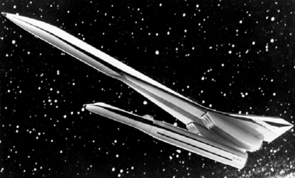 Figure 2.TAS with an expendable third stage as booster rocket. [3] © Dassault Aviation |
For both versions, the second stage was carried under the first stage, which roughly looked like the Concorde jet as illustrated in Figure 2. Lifting the second stage under, not above, the first stage might seem unusual but it was rationalized with previous experiences and tests with the Mirage IV plane dropping nuclear bombs at high speed. TAS designs were heavily influenced by Dassault’s previous supersonic experiences. [4]
Takeoff was planned from normal airfields to eliminate costly, rocket infrastructure. The cost of the combined system was hard to gauge but some argued it should be similar to the Concorde. [5] Both stages had ejection systems for the crew. The second stage was designed for a crew of two.
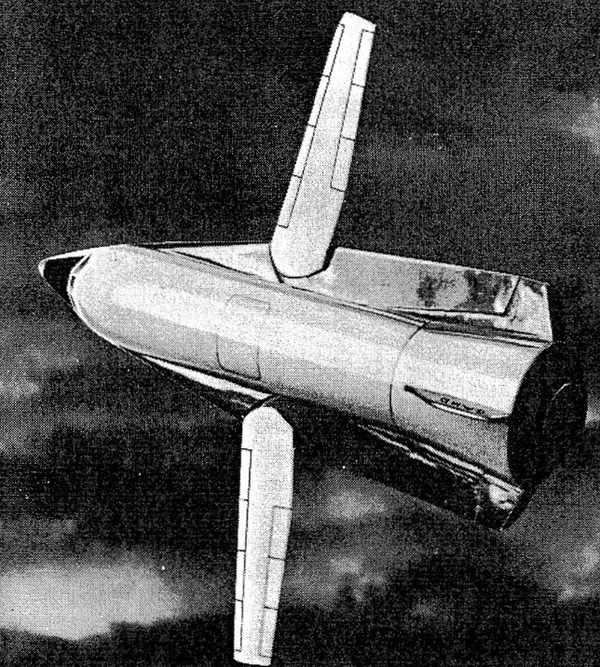 Figure 3. The TAS second stage orbiter [5] © Dassault Aviation |
Six turbofans and turbofan-ramjets were the preferred option for the booster stage until Mach 4.5. At that point, the second stage liquid oxygen/liquid hydrogen (LOX/LH2) engine with an assumed Isp of 435 seconds would ignite and the combined vehicle would accelerate till Mach 6 and 40 kilometers high, where it separated. To prevent the second, orbiter stage from arriving in orbit with empty tanks, the first, booster stage was augmented with extra LOX/LH2 tanks front and aft which would be used in this stage of flight. These days, this is sometimes referred to as “cross-feed”.
| The payloads were small compared to the structural masses and the fuel fraction half of a vertically launched orbital rocket. |
Acceleration was limited to less than 3Gs per Eurospace study instructions. For reentry, the second stage had a special alloy heat protection which would have required refurbishment after every flight. The second, orbital stage in Figure 3 was designed with a variable wing geometry like a fighter jet to improve the lift-to-drag ratio during reentry. [3]
Payload to orbit was only about 1 ton plus a dV in orbit of 3,300 feet per second (1,000 meters per second ) when mass was allocated to fuel for orbital maneuvers. If no orbital maneuvers where required then the payload increased to about 2.5 tons in the partial reusable case and four tons for the full reusable version.
In terms of mass fraction tuples, the TAS-150 was roughly summarized as (0.59, 0.40, 0.01) and TAS-230 as (0.39, 0.60, 0.01). The payloads were small compared to the structural masses and the fuel fraction half of a vertically launched orbital rocket.
Le Mistral
“Le Mistral” in Figure 4 was a TSTO study by the French Nord-Aviation, SNECMA, and the German ERNO roughly between 1964 and 1966. [30] Similar to the Dassault concept, it started horizontally. The first stage was designed by Nord-Aviation and had obvious similarities with the Concorde supersonic plane. For comparison in Figure 5, the Concorde was planned to have a takeoff weight of 148 tons.
The Mistral air-breathing first stage with four turbo-ramjet engines planned to accelerate to Mach 7 before separation at 115,800 feet (about 35 kilometers). Takeoff weight was 200 tons, with the first stage 120 tons (52 tons of propellant) and second stage 77 tons (62 tons of propellant). The first stage was planned to have a length of 51.8 meters with 72 tons of thrust. [12] The second stage was carried under the first stage and was 25.9 meters long with six LOX/LH2 engines. The system in Figure 4 and 5 was prominently displayed at the 1965 air show at “Le Bourget” near Paris, France. [6,9]
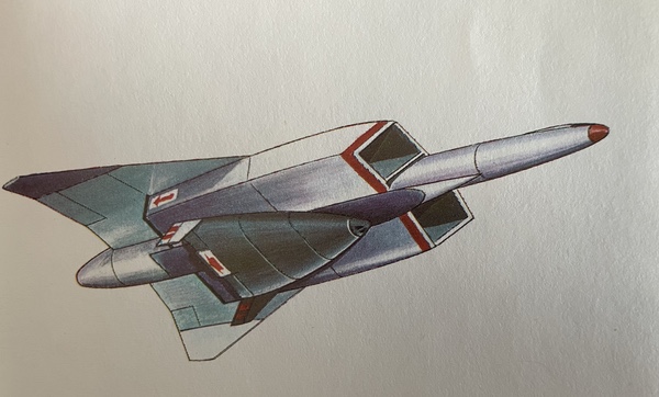 Figure 4. “Le Mistral” French-German (ERNO, Nord-Aviation,SNECMA) concept 1964. [12] |
A later source says that the first stage was redesigned and now would accelerate to Mach 6.5 at 35 kilometers height with an angle of about 15 degrees before separation. For thermal control, transpiration cooling and ablation were studied. Although the system would be fully reusable, an expendable thirst stage rocket was considered. [14,30]
The Mistral was summarized in terms of mass fractions as (0.47, 0.51, 0.02), which are more similar to an airplane than a rocket. Whether the second stage should be carried in a first-stage payload bay for heat and aerodynamic reasons remained an open question. [10]
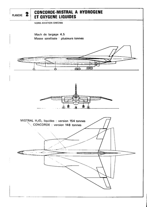 Figure 5. Mistral summary. [10] |
MUSTARD
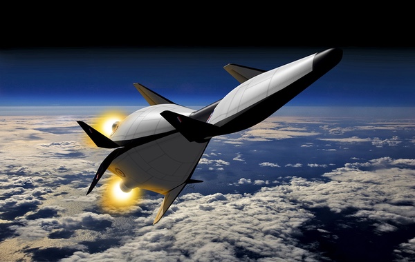
From the United Kingdom and illustrated in Figure 1, there was a 1964 Aerospace Transporter contribution by the British Aircraft Corporation (BAC) with a VTOHL concept named the Multi-Unit Space Transport And Recovery Device (MUSTARD). [15,33.v] While different compared to most HTOHL concepts, BAS considered the rocket-powered vertical takeoff an advantage based on its earlier air-breathing horizontal takeoff studies.
The concept was vaguely inspired by the contemporary Douglas “Astro” concept and possibly the NASA M-2 flying body. With a takeoff weight of about 450 tons, it was projected that a payload of about three tons would be delivered to a 300-nautical-mile (555-kilometer) orbit. The system was 35 meters high and composed of three almost identical boosters. Three copies of the single vehicle design would be “clicked” together and launched, after which one of them would continue to orbit. [7,13]
Each vehicle had a central LOX tank and LH2 titanium tanks in the wings. This triamese design used propellant cross-feeds between the units. Various geometries were suggested and the most ingenious looked like a cake split into three slices of 120 degrees each. Alternatively, the three boosters in the cylinder form would carry a fourth unit on the top to orbit as vividly illustrated in Figure 1.
The one or two pilots would sit up front. Some design variations included a “pop out” jet engine on top to maneuver after reentry and before landing. Each unit had four engines clustered together. Booster burn out was projected at 150,000 feet (about 45 kilometers) with a velocity of 6,600 feet per second (about 2 kilometers per second). [7] The available reports point to mass fractions such as (0.15, 0.84, 0.01), which seems like a very small payload fraction.
Another HTOHL British concept came from Hawker Siddeley Aviation but details are scarce. [6,8,26]
Junkers “Sänger I”
With respect to the German Aerospace Transporter studies, the story is really a combination of people, companies, and “zeitgeist”. Legally, after World War II, space and rocket research could only commence in West Germany around 1954. [11] As most experienced rocket engineers had left for the USA and USSR in 1945, a generation was missing when fledging aerospace companies commenced a new start around 1960.
The new generation worked in companies such as Junkers GmbH and Bölkow in the Munich area, the Entwicklungsring Nord (ERNO) in Bremen, and Dornier. Junkers privately funded and studied an early space transporter concept since about 1960. [ 23, 24] It was the first such project in West Germany at the time and based on earlier ideas by Eugen Sänger, who was enlisted as consultant. Therefore, this concept is sometimes referred to as “Sänger I”.
The concept in Figure 6, named RT-8 for “Raumtransporter-8”, was envisioned to use a steam-based catapult start like on an aircraft carrier. The three-kilometer-long catapult used a 2G acceleration to produce a liftoff speed of 500 meters per second at 15 degree angle for the complete system.
At 50 kilometers altitude and around Mach 4, the two stages separated and the second stage ascended to a circular 300-kilometer orbit. Both stages were reusable and would return and land horizontally like planes. The first stage had three LOX/LH2 engines with 295 kilonewtons of thrust and 430 seconds of specific impulse, while the second stage had one similar engine. The first stage had two pilots and second stage one or two. [17,22]
| A driver for piloted and man-rated stages was that computers were not powerful enough at the time to do the landing and rendezvous. |
A small team drove most of the work on the Junkers Aerospace Transporter. Led by Julius Henrici and Jürgen Lambrecht, who was freshly hired from Aerojet in the United States, and later Ernst Högenauer, who joined the Junkers team in 1961 and became the head of space division at Messerschmitt-Bölkow-Blohm GmbH (MBB). [19,21]
In 1962, the German government started an umbrella national research program “Forschungsprojekt 623 Raumtransporter”, abbreviated as “FSK 623” or “FKZ 623”, to coordinate the German work on the Aerospace Transporter. [18,23-26] This also encapsulated the early Junkers work and the Eurospace studies.
In 1963, the goal was to study a reusable carrier with a payload of three to five tons to an orbit of 300 to 500 kilometers. [23] Parameters like number of stages, engine type, propellants,s and takeoff methods were studied alongside of tracking and rendezvous in orbit.
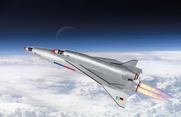 Figure 6. Junkers RT-8-01. [16] |
One conclusion was that an earlier concept for a one-stage spaceplane with catapult start and fluor-hydrazine propellant (F2/N2H4) would not result in an economically useful payload to orbit. Hence work in 1963 concentrated on multi-stage solutions.
A driver for piloted and man-rated stages was that computers were not powerful enough at the time to do the landing and rendezvous. Furthermore, three-stage solutions did not add significant payload in their studies, which is why two-stage solutions were preferred. The engine selection struggled between LOX/LH2 rockets and air-breathing engines based on the staging velocity, but ultimately they preferred the LOX/LH2 for both stages.
A horizontal start with catapult launch was still under consideration. However, it would negate one of the main advantages of “aircraft like operations” and limit the takeoff locations.
Towards the end of the studies, seven different multi-stage systems, A to G, were thoroughly analyzed. [25]. All could deliver about three tons of payload to LEO. The takeoff weights varied between 162 and 460 tons. Unpractical choices like nuclear stages and supersonic combustion were not considered. System A used a catapult start like RT-8 and was projected to be the cheapest to construct. System G had the smallest takeoff weight but required unavailable air-liquidification engines.
System F was more practical. With a combined takeoff weight of 230 tons, roughly 180 tons for stage 1 and the rest for stage 2, a staging speed of Mach 7.5 was envisioned. While this was one of the more costly systems to construct, it had the most spinoff possibilities including hypersonic passenger transport. On a visual basis, it looked similar to Figure 6.
| While projects like the Aerospace Transporter are probably still too large for single European countries or companies, Europe and ESA should keep the Aerospace Transporter findings in mind and build on this legacy with a uniquely, innovative European approach to access space. |
Interesting observations included that the development costs scaled roughly with the staging speed Mach number, more stages meant more complication, and any hypersonic air-breathing solution at least twice as costly compared to better understood LH2 rocket engines. [25]
Based on the available reports, with sometimes conflicting mass and other numbers, the mass fractions seem to be about (0.15, 0.82, 0.03). Studies in 1964 would optimize this design. Again, this was a small payload but with a fuel fraction much closer to a modern airplane.
Conclusion
Sixty years later, construction materials have improved and better structural mass fractions seem achievable. Keep in mind that certain materials like titanium hulls would improve the empty mass fraction but might make the construction costs very high. The tradeoff between mass, economics, and missions is still very much the same as in the past.
While “mass to orbit” is important for many, there could be a market for smaller and more versatile transporters. For example, in daily life many people have a car to get around but there is a market to zip around on electric scooters, which almost no one envisioned a decade ago. While projects like the Aerospace Transporter are probably still too large for single European countries or companies, Europe and ESA should keep the Aerospace Transporter findings in mind and build on this legacy with a uniquely, innovative European approach to access space. [32]
References
[1] E. Sänger, N64-32878#, “Aerospace Transporter”, by EUROSPACE Working Group III, “Technical Studies” at National Aerospace Library, Farnborough (UK), CID 59959, 58 pages, October 1964.
[2] E. Sänger, “The Historical Background and Motivation for a European Aerospace Transporter Proposal”, at The Eurospace Conference on the Aerospace Transporter, 23-24 January 1964, Brussels, Belgium. 10p.
[3] P. Coué, M. Rigault, “Dassault Aviation’s Aerospace Transporter an historical perspective”, 6 pp, id 7024, IAC-10.E4.3.7, 44th History of Astronautics Symposium, IAC 2010, September 2010.
[4] P. Coué, “Dassault Aviation, designer of spaceplanes”, 8 pp, IAC-22-E4.3.69225, 73rd International Astronautical Congress (IAC), Paris, France, 18-22 September 2022.
[5] H. Deplante, P. Perrier, “A French Concept for an Aerospace Transporter”, Space Technology Conference, SAE 670388, February 1967.
[6] H. Tolle, “Review of European Aerospace Transporter Studies”, Space Technology Conference, SAE 670385, pp 120-128, February 1967.
[7] T.W. Smith, “A British Reusable Booster Concept”, British Aircraft Corporation (BAC), Space Technology Conference, SAE 670389, pp 159-167, February 1967.
[8] R. H. Francis, “Air-Breathing Reusable Launchers”, Hawker Siddeley Aviation Ltd. SAE 670390, pp. 169-174, February 1967.
[9] “Europe Firm on Space Transporter Goals”, Aviation Week & Space Technology, pp 77-78, June 28, 1965.
[10] T. Moulin, “L’avion lanceur de satellites”, Icare, n.50, pp 56-68, 1969.
[11] H. E. Sänger, A. D. Szames, “From the Silverbird to Interstellar Voyages”, IAC-03-IAA.2.4.a.07, 54th International Astronautical Congress of the International Astronautical Federation, the International Academy of Astronautics, and the International Institute of Space Law, 29 September 2003, Bremen, Germany.
[12] P. Bono, K. Gatland, “Frontiers of Space”, 279 pages, ISBN 978-0025428102, 1976.
[13] “Reusable Launch Systems”, Astronautics & Aeronautics, January 1964.
[14] J.C. Carbonel, “French Secret projects”, “French and European Spaceplane Designs 1964-1994”, ISBN 9781910809914, 2021.
[15] D. Sharpe, “British Secret projects”, “Britain’s Space Shuttle”, ISBN 9781910809020 , 2016.
[16] K. Rainer Deutsches Museum, Digital neu zusammengestellt von birkho, CC BY-SA 4.0 via Wikimedia Commons.
[17] “Junkers / Raumtransporter Junkers RT-8-01”, 1961.
[18] H. Billig, “Forschungsprojekt 623, Raumtransporter”, ERNO, 124 pages, Bundesarchiv BArch B 228/13832, December 31, 1962.
[19] “ESA oral history of Europe in space”, “Interview mit Ernst Högenauer”, ESA INT68, 15 pages, 2010.
[20] “The DORIAN files revealed : A compendium of the NRO’s Manned Orbiting Laboratory documents”, edited by James D. Outzen, Ph.D., incl. Carl Berger’s - “A History of the Manned Orbiting Laboratory Program Office”, Aug. 2015.
[21] J. Lambrecht, “Probleme bei der Verwirklichung eines einstufigen Raumtransporters”, presented at “3rd European space flight symposium”, Stuttgart, Germany, 1963, in English “Design problems for a one-stage transporter”, 20 pages, N71-71498, NASA TT-8573, NTRS 19710066184, November 1963.
[22] “Junkers GmbH RT (Space Transporter, Saenger)”.
[23] “Junkers Arbeitsbericht 1963: Band 1,2 and 3. Forschungsprojekt 623 Raumtransporter”, RFT 32, 537 pages, Bundesarchiv BArch B 228/2985, 228/2986, 228/2987.
[24] J. Henrici, “Forschungsvorhaben 623, Träger- und Raumflugsysteme, Technische Studie eines Raumfluggerätes RVI/623/01/64 und RFT 32/1963”, 188 pages, Bundesarchiv BArch B 228/7823. https://invenio.bundesarchiv.de/invenio/direktlink/a96b0788-dbbb-498e-a1ca-8bb4118a2e9d/
[25] J. Henrici et al,”Forschungsvorhaben 623, Studie über wiederverwendbareTrägersysteme” “RV 3 - 623/01/65”, 87 pages, München, April 1966, Bundesarchiv BArch B 228/1762.
[26] “Jahresbericht 1963 des Forschungsprojektes 623 Raumtransporter-studien”, 185 pages, Bundesarchiv BArch B 228/2984, 1963.
[27] J. Lambrecht, “Auslegungskriterien des Raumtransporters”, in “Projektstudie 623, Raumtransporter-Symposium”, 34 pages, pp 58-90, KPAR-A720, München, Germany, March 1964. https://dlr-archivkatalog.bsz-bw.de/cgi-bin/koha/opac-detail.pl?biblionumber=2197
[28] J. Lambrecht, E. Schäfer, “A West-German Approach to Reusable Launch Vehicles”, Junkers FMW, Space Technology Conference, SAE 670387, pp. 144-148, February 1967.
[29] R. Nah, “A Comparison of Fixed Wing Reusable Booster Concepts”, Convair, Space Technology Conference, SAE 670384, pp. 99-111, February 1967.
[30] J. Hasseloff, “Untersuchungen zum Raumtransporter und zur Rückführung der Oberstufe”, “ERNO Forschungsbericht W 69-23”, N69-37772, 88 pages, Juni 1969.
[31] J.E. Love, W.R. Young, “Operational Experience of the X-15 Airplane as a Reusable Vehicle System”, NASA, Space Technology Conference, SAE 670394, pp. 198-204, February 1967.
[32] S. Stappert et al, “European Next Reusable Ariane (ENTRAIN): A Multidisciplinary Study on a VTVL and a VTHL Booster Stage”, DLR, 70th International Astronautical Congress (IAC), Washington DC, United States, IAC-19-D2.4.2, 17 pages, 21-25 October 2019.
[33] The Eurospace Conference on the Space Transporter, 23-24 January 1964, Brussels, Belgium. All were presented at the conference. They have NTIS accession numbers via STAR but no copies located yet except (*).
i. N65-23958#, Maurice Roy, “Minutes of the Technical Meetings held during the Eurospace conference in Brussels on the Space Transporter”, also called “Aerospace plane transporter systems engineering, structural designs, and cost estimates”, Eurospace Report-6525, Eurospace, Paris (France), 32p.
ii. N65-23959#, M. Kaufmann,”HIGH PRESSURE ROCKET POWER UNITS FOR SPACE TRANSPORTERS”, Bölkow Entwicklungen K. G.. Munich. (West Germany), 14p.
iii. N65-23960#, D.G. Thomas,”PERSONNEL SUB SYSTEMS”, Martin Co., Baltimore, Md., 23p.
iv. N65-23961#, M.B. Dunn, “STRUCTURES PROBLEMS OF SPACE SYSTEMS”, Boeing Co. Seattle Wash, Aero-Space Div, 27p.
v. N65-23962#, T.W. Smith, “ENGINEERING PROBLEMS OF NEAR FUTURE HYPERSONIC VEHICLES”, British Aircraft Corp., London, England, Preston Div, 18p.
vi. N65-23963#, J.C. Peters, “SPACE LAUNCH VEHICLE COST CONSIDERATIONS”, United Aircraft Corp.. Farmington, Conn. Corporate Systems Center, 17p.
vii. N65-23964#, Max A. Hauzeur, “THE SPACE TRANSPORTER--GENERAL MISSION ANALYSIS”, Sociétés Anonyme Belge de Constructions Aéronautiques (SABCA), 8p .
viii. N65-23965# George Mounis, “OUTLINE OF METHODS AND DATA REQUIRED FOR HEAT SHIELD CALCULATIONS”, Sud-Aviation, Paris (France), 31p.
ix. N65-24024# R.J. Lane, C.J. Austin, and M. J. Welch, “COMPARATIVE METHODS OF SPACE BOOSTING”, Bristol Siddeley Engines, Ltd. (England). Advanced Propulsion Research Group, 25p.
x. N65-24027# J. Tubeuf and J. Bedel, “CONSIDERATIONS ON ROCKET PROPULSION FOR AN AEROSPACE VEHICLE”, 29p.
xi. N65-24031# J. Lambrecht, “COMPARED COSTS OF SPACE TRANSPORTERS AND OF BOOSTER ROCKETS”, Junkers Flugzeug- und Motorenwerke A. G.. Munich (W. Germany), 15p.
xii. N65-22883#, P.O. Hawkins, “ELECTRONIC ASPECTS OF SPACE TRANSPORTER”, Elliot Bros. Ltd., London (England), 8p.
xiii. N65-23324# H. Deplante and P. Perrier, “ABOUT A CONCEPT OF AN AEROSPACE TRANSPORTER”, Dassault (Marcel) Aeronautique-Electronique (GAMD), France, 10p.
xiv. E. Sänger, “The Historical Background and Motivation for a European Aerospace Transporter Proposal”, 10p. (*)
Note: we are now moderating comments. There will be a delay in posting comments and no guarantee that all submitted comments will be posted.