Science Power Platform: the ISS’s cancelled power moduleby Maks Skiendzielewski
|
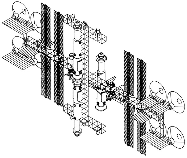
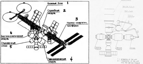
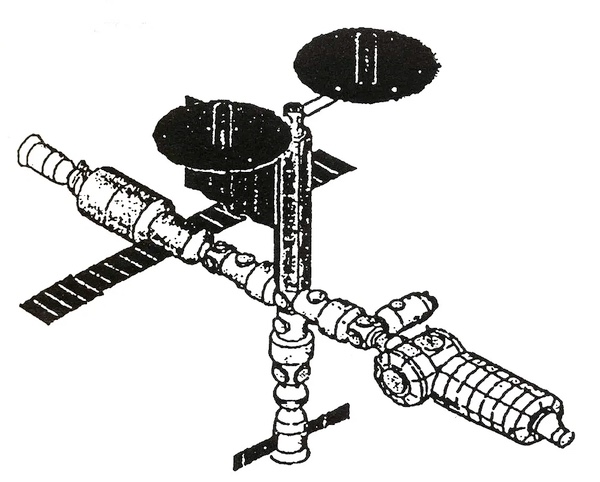
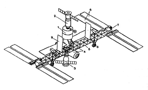 Mid-1992 configuration of Mir-2 with the in-space assembled Science-Power Platform truss, in the all-photovoltaic variant on the top and with solar concentrators on the bottom. Images: Novosti Kosmonavtiki, Aviation Week and Space Technology. |
Another part with Sofora heritage were the two orientation thruster blocks, which were similar in design to the VDU roll control thruster mounted at the end of the Sofora truss.
Closer to the center, two large radiators were mounted and, opposite the thruster blocks, sat mobile experiment platforms that could orient the experiments as required; on Mir, some experiments required that the entire station be reoriented to point the instruments.
Providing power to the Mir-2 complex were four pairs of photovoltaic Reusable Solar Arrays (MEB) of the same design that flew on Mir’s Kristall module and later with the Mir Docking Module, though at a later stage of assembly on one side of the truss the arrays would make way for a pair of parabolic solar concentrators.
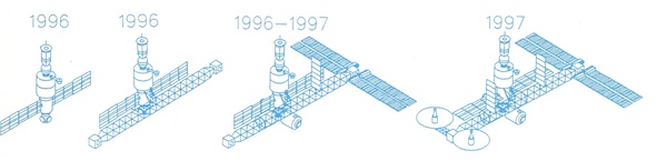 Assembly sequence of the 1992 Mir-2 design. Image: Aviation Week and Space Technology. |
The concentrators work by focusing sunlight onto a circuit of working fluid that expanded and drove a turbine—alas, even in space every new method of energy generation is a steam turbine. The main advantages of the solar concentrators cited by NPO Energia representatives are the reduction of the area needed to generate the same power by more than a factor of two, lower mass, and decreased atmospheric drag. In this configuration, assembly of the station was due to begin in 1996 and be completed within three years, with the solar concentrators joining the station as early as late 1998.
In mid-1992, talks between ESA and Russian space program officials on deeper cooperation intensified, with the European agency eyeing Mir-2 as the destination for the Russified version of the Man-Tended Free Flyer (MTFF), which had just been dropped from the plans for Space Station Freedom, and a new collaborative Euro-Russian spacesuit. When the Hermes spaceplane was cancelled later in 1992, they agreed to salvage the technology for its robotic arm, the HERA (HErmes Robotic Arm), and use it on Mir-2. The renamed European Robotic Arm (ERA) appeared in the station’s design in late 1992/early 1993, attached to a mobile platform that could slide along the length of the truss, similarly to how Canadarm2 operates on the ISS.
 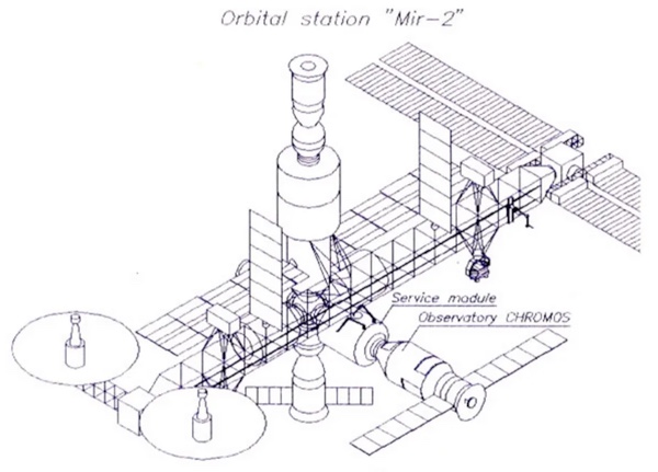 Top: Illustration of the early Hermes Robotic Arm (HERA) in use on the Hermes spaceplane. Bottom: Late 1992/early 1993 illustration of Mir-2 and the Chromos observatory showing the appearance of the ERA and its mobile platform on the station’s truss. Images: ESA/Fokker, garni-cosmos.com |
Octagons!
By May 1993, illustrations distributed to the media showed a significant change in the design of the truss. While still attached to the side of the core module, it was now octagonal in cross-section and made up of a handful of large, pre-assembled segments, though it is unclear if these would fly on Zenit or possibly Buran—work on the Soviet orbiter had by that time slowed to a crawl due to funding issues and was completely abandoned later that month.
Western officials and experts had been eager to point out that the previous hand-assembled truss would have been a major challenge for the cosmonauts had it remained in the final configuration. Freedom itself transitioned to pre-integrated truss segments in 1991 in part due to a whopping 2,000 to 3,000 hours of EVA required every year to build and maintain the station with its original truss, according to studies commissioned by NASA.
 The interim Mir-2 configuration of 1992. Images: Novosti Kosmonavtiki, ESA via danielmarin.naukas.com |
Final Mir-2 configuration
In an effort to make station expansion easier, provide more docking ports, and allow for a potential swap of the core module after it outlived its usefulness, two Universal Docking Modules (USMs) were added to Mir-2 in mid-1993 and the orbital complex took on the form most familiar to space nerds. USM №1 would be attached to the core module’s forward port with the two halves of the octagonal-section Science Power Platform berthed to its lateral docking ports: the SPP was now “intersecting” the pressurized module instead of being braced against the core module’s side.
 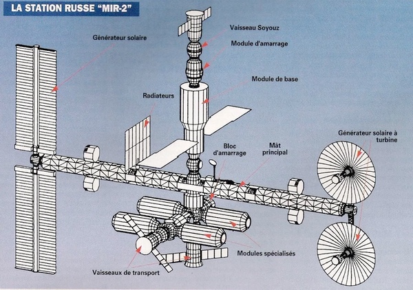 The 1993 Mir-2 configuration. Images: ESA via danielmarin.naukas.com, capcomspace.net |
Each half of the Science Power Platform was made up of two large segments: the first was docked to the side of USM №1 and contained a pressurized compartment that provided space for control moment gyros and electrical batteries as well as the mounting points for the large 8.4-by-6.0-meter radiators; the second section contained a narrower extendable truss that was deployed to its full length once the module was berthed to the station. The segments would be paired with Progress-derived tugs and launch on Zenit.
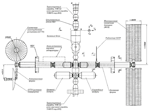
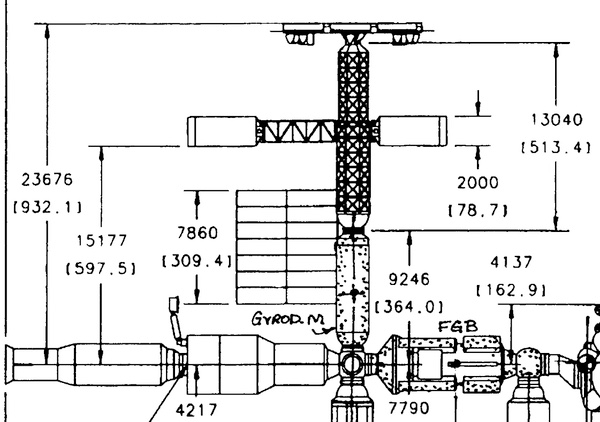
 General layout and dimensions of the Mir-2 truss. Image: ESA via danielmarin.naukas.com |
Attitude thruster packs, now named the Remote Propulsion System, were once again mounted on the SPP, but by this point they had changed their shape to octagonal prisms that would fly inside the unpressurised volume of the first SPP segment and be repositioned on the truss using the robotic arm. Just like before, power was provided by a mix of photovoltaic arrays at one end of the truss and parabolic solar concentrators at the other; both had two degrees of freedom to allow them to be pointed towards the Sun more efficiently—the original Mir had become so power-starved by the late ’90s that often the entire station needed to be reoriented to produce the power required.
  Images ESA via danielmarin.naukas.com |
Merger of equals?
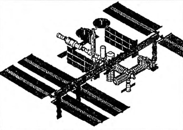
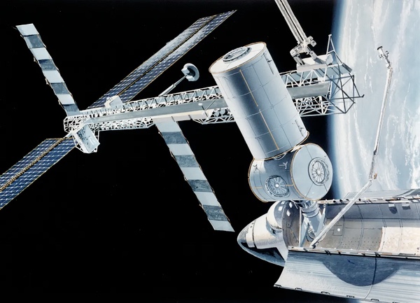
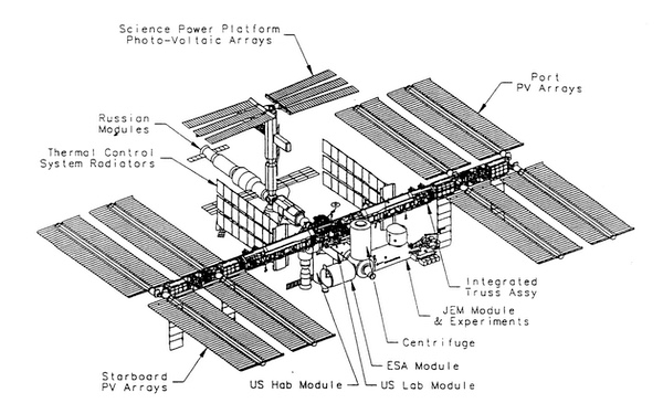
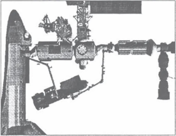
In the meantime, discussions on merging the financially unstable Mir-2 and Freedom (renamed to Alpha after the 1993 redesign) projects had been intensifying and finally culminated in an agreement to combine the two stations. The initial configuration of the new international Space Station Alpha unveiled on August 26, 1993, included most of the Space Station Freedom hardware—dubbed the US Orbital Segment—and a smattering of Russian pressurized modules with half of Mir-2’s Science Power Platform docked to the zenith port of one of the three Universal Docking Modules now present on the station, which formed the Russian Orbital Segment.
  Images: Novosti Kosmonavtiki |
Interestingly, the new Science Power Platform used solar concentrators instead of the more conventional photovoltaic arrays. While they did promise a higher power output, they also required additional heat rejection capacity, so the American side quickly requested they be downsized from 10 kilowatts to just 2–3 kilowatts, which the Russians promptly rejected as it negated the whole point of using solar concentrators to generate a lot of power.
More criticism came from NASA engineers, who doubted that the system could be developed in just a couple of years and join the station early in the assembly process: the illustration above on the right is not just a cutaway or partial view, but how the station would have looked just before the US side started building the Integrated Truss Structure with its large solar arrays.
One of the incentives for inviting Russia to the project was, along with lowering the station’s burden on the American taxpayer, the ability to reach “Permanent Manned Capability” (PMC) much sooner than with the revised Freedom. Instead of assembling the truss from one end, adding pressurized modules in the middle and only reaching PMC after 11 or so assembly flights, permanent crew occupation could start as soon as the first US modules were attached to the Russian segment and electrically connected to the Science Power Platform, which was scheduled for the fourth shuttle flight to the station. The main truss could then be built from the center out.
 1993 configuration of Freedom at Man-Tended Capability (achieved after six Shuttle flights). Image: NASA via National Archives |
By autumn 1993, the solar concentrators on the SPP were replaced with the photovoltaic arrays from the other end of the Mir-2 truss, though a possibility was left for the concentrators to join the station at a later stage, when they would be attached to the shorter end of the American truss. By the end of the year, after plans to test demonstrators of the concentrators on Mir (predictably) fell through, the technology’s inclusion in the space station design was abandoned altogether.
In October 1993, two of the three Universal Docking Modules were replaced by a single Functional Cargo Blok (FGB), later named Zarya, and the Science Power Platform migrated to the FGB’s zenith docking port. On November 1, 1993, the “Addendum to the Space Station Alpha Program Implementation Plan” containing the new design was officially approved and presented at the White House.
 1 November 1993 configuration of the space station. Image: NASA via danielmarin.naukas.com |
Before the end of 1993, the Science Power Platform was moved from Zarya to the zenith docking port of the Service Module—the ex-Mir-2 core module, later renamed Zvezda.
 The SPP in its new location on the station. Note the solar concentrators on the American truss. Image: NASA via National Archives |
The SPP retained its late-Mir-2 structure and required three launches on the Zenit: one each to carry the two truss segments and one carrying a modified Progress spacecraft with a special cargo platform holding now six solar arrays, and control moment gyros.[1] A special rail for the ERA would be mounted on the Universal Docking Module and the SPP to allow the components delivered on the third launch to be transported to their mounting location on top of the SPP. All three launches were planned for September-October 1997 as of early 1994.
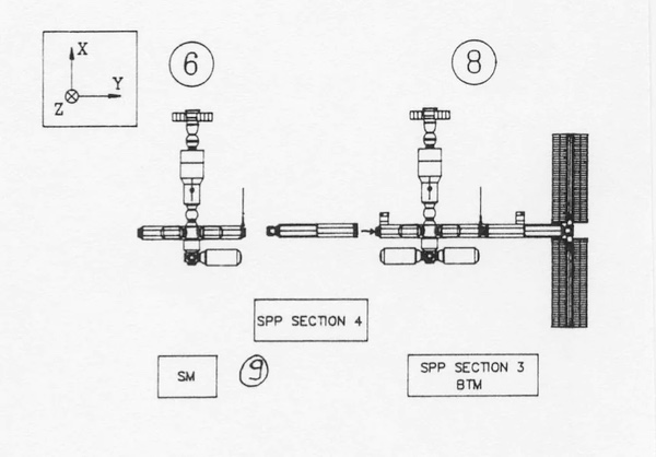
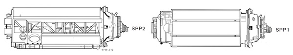
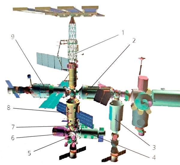
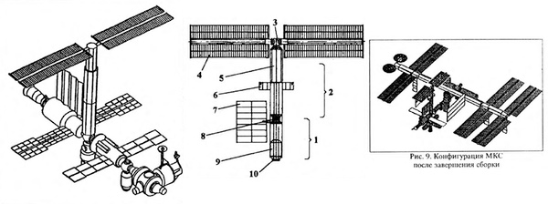 Early 1994 configuration of the space station. Middle: Legend: 1 — SPP-1 segment; 2 — SPP-2 segment; 3 — two-axis solar array joint; 4 — SPP solar array; 5 extendable part of the SPP-2 segment; 6 — remote propulsion system; 7 — radiator; 8 — docking point of SPP-1 and SPP-2; 9 — pressurised compartment with control moment gyros; 10 — docking point of SPP-1 with Service Module. Right: a one-off illustration with the SPP turned 90 degrees. Images: Novosti Kosmonavtiki |
Consolidation
By early 1994, the ISS regained the fourth solar array pair on its main truss, while the Science Power Platform design evolved. Information on this version is very scarce, but all illustrations show a somewhat simplified structure, with the extendable section replaced by a single long unpressurised truss. Instead of the octagonal Remote Propulsion System attitude control units, the SPP now utilized new Autonomous Thruster Facility (ATF) packs. Each ATF unit would house its own propellant tank, for a total of 1,760 kilograms of propellant across two units, of which 1,680 would be usable. The attitude thrusters on the ATF seem to be the NIIMash 11D428A-16 units with about 130 newtons thrust and 290 seconds of specific impulse, also used on Zvezda and the Soyuz service module.
This propellant mass might not seem huge for a station of this size, but the ATF thrusters would have been over 15 meters away from the orbital complex’s center of mass, which massively improves their effectiveness, especially for roll corrections. In fact, the same fuel-saving trick is currently being used with thrusters on the Nauka module.
  1995 configuration of the ISS with the Science Power Platform and Autonomous Thruster Facility units. Images: NASA via NTRS |
As in the previous plan, the main truss would be launched on two flights of the Zenit, but now the second flight would also carry the first ATF unit. A total of four ATF units, all launching fully-fueled, feature in the flight planning documents, despite drawings and diagrams of the station’s layout only showing two units. Completely replacing the first two units just two years after launch seems unrealistic, so there must be a different explanation. I have not, unfortunately, been able to find it.
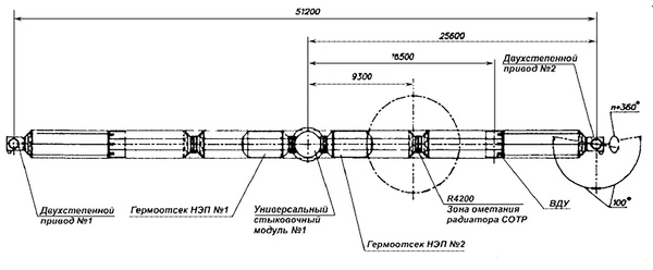
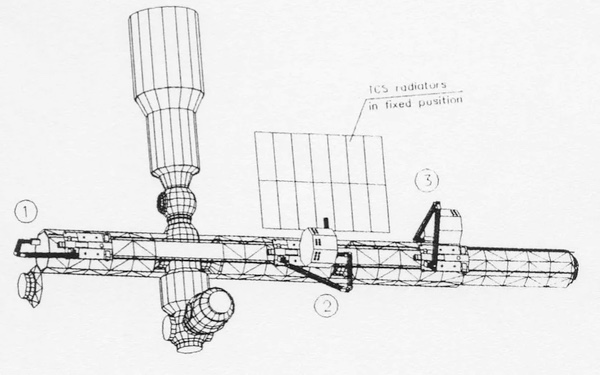
 A diagram of the two Science Power Platform segments in the 1994–1995 Zenit-launched configuration. Image: NASA |
As of 1995, the launch of the first SPP truss segment (assembly flight 5R) was scheduled for November 1998, followed by flight 6R with the second truss segment and first ATF unit in February 1999. The first solar arrays would be delivered on flight 7R in April 1999. After a short break, SPP assembly would resume with flight 12R in November 2000, carrying two ATF units and flight 14R in October 2001 would deliver the final fourth ATF unit and the remaining solar arrays.
The solar arrays would launch aboard a dedicated Progress-derived cargo spacecraft launched on Zenit and, after arriving at the station, would be moved to their mounting point with the help of the ERA along the special rail running down the truss and the Universal Docking Module below.
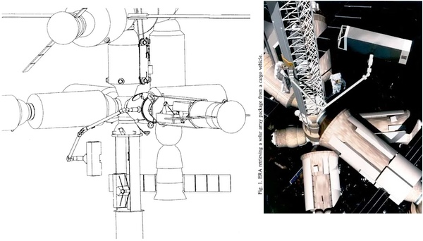 Solar array delivery for the Science Power Platform aboard modified Progress spacecraft. Images: Robotics and Autonomous Systems, ESA |
New launcher, new platform
The adopted assembly sequence emphasized Russian modules in its early phase, with a gradual shift of the balance towards American segment hardware later. For Russia’s strained space industry, the idea of supporting both the Mir program and the new ISS at full force was considered unfeasible, so after all shuttle flights to Mir were successfully completed, the orbital complex was to be abandoned in 1997, with all efforts redirected towards building the ISS henceforth.
However, there was still some useful life left in the Mir complex—two modules, Priroda and Spektr, had not even been launched yet—and the RKK Energia proposal to start assembling the ISS by adding new modules to Mir and discarding the old hardware later was rejected by NASA. So, by 1996, the Russians started pushing for a simplification of the Russian Orbital Segment to allow the simultaneous operation of Mir and the ISS during the initial phase of the latter’s construction until the end of the decade.
In January 1996, a delegation of Russian government and industry personnel travelled to Houston and reached an agreement for the US to join in on the utilization of Mir until 1999 and for both countries to fully shift focus to the nascent ISS thereafter. The Russian side also announced that to maintain the launch schedule they would abandon the use of the Zenit launch vehicle for ISS assembly, citing high launch costs and the availability of just one launch pad in Baikonur suited for the Zenit. The SPP would now be delivered to the ISS on two flights of the shuttle.
In March 1996, the feasibility of launching the SPP on the shuttle was confirmed and, in May, the preliminary design of the module was presented to NASA officials in Moscow. Revision B of the ISS Assembly Sequence document scheduled the first SPP mission for flight 9A.1 in November 1999.
The change of launch vehicle necessitated a thorough redesign. The new Science Power Platform retained the pressurized section (Block A) from the previous version, but now the entire module would launch pre-integrated, with the truss section (Block B) mounted directly to the pressure hull.
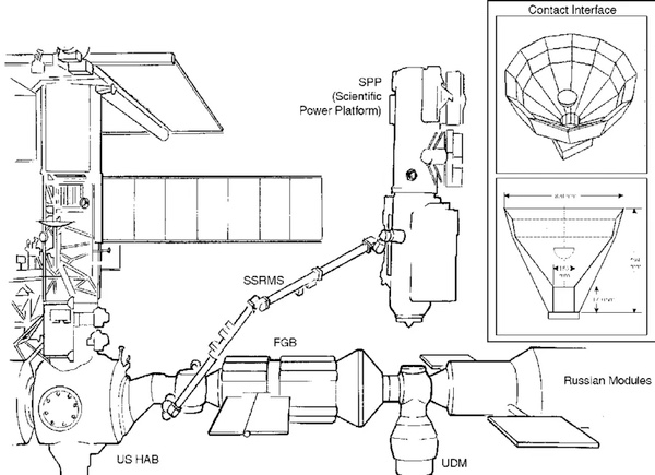
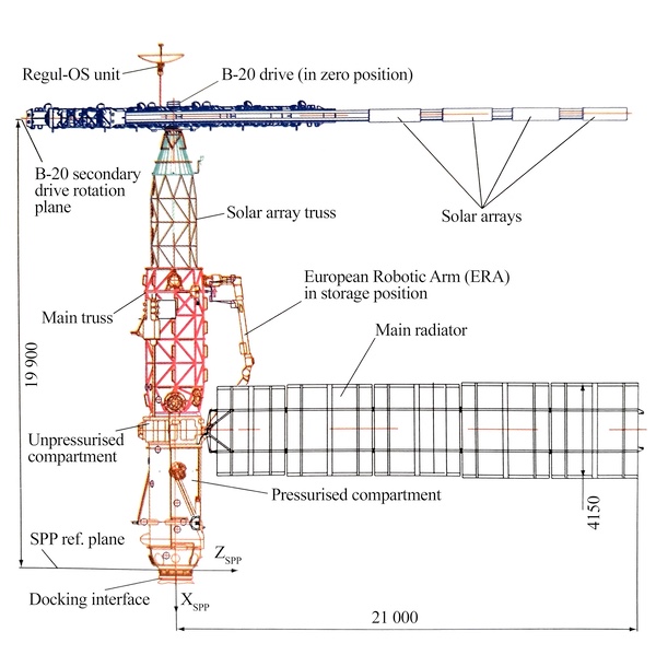 General layout of the Science Power Platform. Image: Semyonov 2001 via Nicolas Pillet, translated by Yours Truly |
Like in the pre-1994 design, a secondary truss would extend from the unpressurized section to provide clearance for the eight solar arrays: four arrays would now launch together with the rest of the SPP, temporarily mounted to the side of the truss, while the remaining four would be delivered together with micrometeoroid shields and extra hardware on the second shuttle flight.
The module would mass around 15 tonnes at launch,[2] which would increase to around 20 tonnes after all outfitting hardware and payloads were installed. In the stowed position, the SPP’s length was 13.45 meters, which would increase to 19.90 meters with the secondary truss fully extended. The pressurized compartment was 5.9 meters long with a 1.0-meter unpressurised compartment directly above it, both with a diameter of 2.20 meters. The extendable truss measured 6.2 meters long and 2.55 meters in diameter.
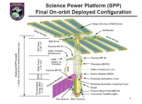 Image: NASA via Wikimedia Commons |
Six gyrodynes would be installed to aid the station’s attitude control, together with orientation thrusters on the truss section. Of course, the design also included some lovely payload attachment trunnions to interface with the shuttle’s payload bay.
  Images: Lopota 2011 via Nicolas Pillet, RKK Energia via RussianSpaceWeb.com |
Shortly thereafter, the Russian Space Agency made the decision to develop a new heavy-duty variant of the venerable SSVP docking port for use on the station’s Russian segment, including the Science Power Platform. The “hybrid” SSVP-M8000 retains the soft-docking “pin-and-cone” mechanism from the standard SSVP-G but borrows the larger and stiffer hard-docking collar from the APAS-89/95 system to cope with the larger forces experienced by the unprecedentedly heavy space station.
The new delivery method also required a unique berthing maneuver. As the shuttle’s Canadarm manipulator would not be able to reach far enough to position the SPP’s over Zvezda’s zenith docking port, the module would be “handed off” to the station’s Canadarm2 and only then berthed at its destination. No spoilers yet, but the “hand-off” would end up being performed for real some 15 years after being conceived for the SPP.
  SPP handoff maneuver and berthing. Images: IFAC Space Robotics, General Contact Dynamics Toolkit |
The European Robotic Arm remained part of the SPP complex, joined by a newly developed manually operated platform that would ride along the truss with one or two cosmonauts. A Regul-OS communications antenna was placed at the top of the truss; when plans were being drawn up for ATV flights to the ISS in 1999, there was briefly a proposal to place the antenna for the MBRL data link for approaching spacecraft on the SPP as well, but the hardware was installed on the Zvezda module instead.
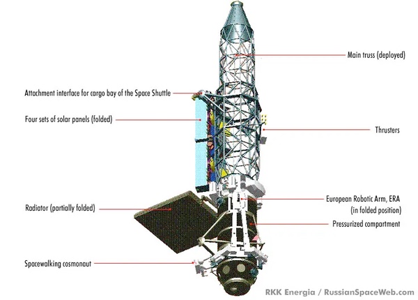
In addition to the 50 kilowatts of power generation, the Science Power Platform featured a five-segment radiator panel running on ammonia—a first for the Russian space industry—capable of rejecting 30 kilowatts of waste heat. The unit measured 4.15 meters at the widest point and extended 21 meters from the module’s centerline.
 Image: ESA (cropped) |
During development of the two-phase ammonia circuit, the phase change behavior and heat transfer dynamics in microgravity proved to be difficult to control, so an experiment was devised to test the system before it was signed off. Named Kontur (circuit in Russian), the full-scale heat exchanger circuit was delivered to Mir on Progress M-42 and tested in the summer of 1999.
The Kontur hardware was mounted on the outside of the Progress spacecraft to avoid the possibility of an ammonia leak finding its way into the habitable volume of the station. Despite a number of hiccups before the experiment even made it to space and some hilarious problems with the hardware when it did—like the discovery that when deployed, the radiator partially obscures the TORU docking antenna and two ammonia lines fall right over attitude thruster nozzles — the function of the system was validated.
Staying true to its name, the Science Power Platform was also designed to house some experiments. In the Russian Orbital Segment’s 1999 configuration with nine modules, the SPP would account for 8% of all science payloads by number, at 24 experiments.
Building the thing…
In 1997 RKK Energia’s Experimental Machine-building Plant (ZEM) started preparations for the manufacturing of the pressurized compartment.
By 1999, significant work was done on the pressure vessel, truss structure, solar panels, attitude control engine pneumohydraulic circuit, the electrical layout, and the control logic, and the testing campaign framework was developed. For the SPP, a new minimum service life requirement of 15 years—double that of Mir hardware—was introduced, which necessitated stricter tolerances and quality criteria.
The ZEM plant was responsible for the assembly of the pressurized compartment, but delegated the fabrication of the pressure hull components and truss elements to the Progress factory in Samara. Outfitting hardware like solar arrays and a cargo boom, as well as final assembly and testing of the SPP remained the responsibility of the ZEM. At least two pressurized compartment hulls were fabricated: one static test article and one dynamic test article.
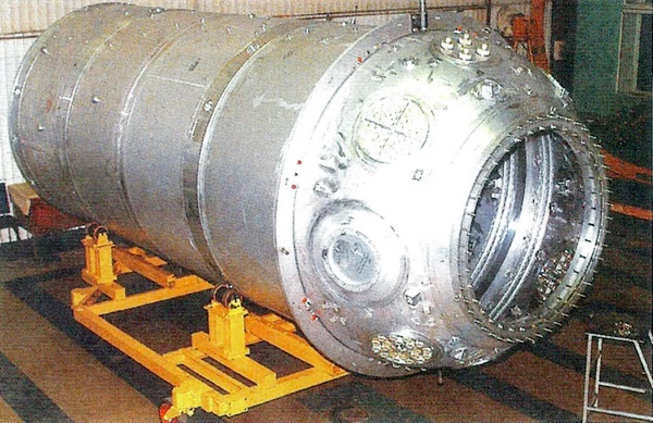  SPP pressure vessels at RKK Energia. Images: Lopota 2011 via Nicolas Pillet |
The pressure vessel itself was divided into three main sections: the hemispherical forward section, the central cylindrical section, and the truncated conical aft section. The cylindrical section was welded from four shorter segments 2.20 meters in diameter. The forward section is essentially the front half of a Soyuz orbital module, with a spherical profile 1.1 meters in radius, though on the SPP the half-dome is densely packed with electrical connector feed-throughs. An active SSVP-M docking unit would be attached at this end.
…slowly
Between 1996 and 1998, work on the Russian segment of the ISS progressed at a very slow pace due to the perennially low funding allocated for the project. In May 1997, the launch of the SPP with the first four solar arrays was scheduled for flight 9A.1 in July 2000, with the remaining arrays arriving on flight 14A in May 2002 together with the ESA-built Cupola. By 1998 those dates had slipped to January 2001 and August 2002.
Work conducted in 1998 and 1999 at a cost of 161.7 million rubles was completely self-funded by RKK Energia as Roscosmos refused to include it in the contract and, in mid-1999, work practically stopped. The 9A.1 flight slipped to November 2001 and the 14A flight, which would now also carry MMOD shields for the Zvezda module, slipped to August 2003.
In early 2000, Roscosmos appropriated less than 25% of the requested amount of funding and, after a short burst, work had to be stopped again. By August, the 9A.1 flight slipped further to October 2002, and the second assembly flight was split into two: dtwo arrays with their beam would now fly on the 1J/A flight in February 2004, with the two remaining arrays joining during flight 14A in May 2005.
By 2001, the Russian Space Agency realized that the plethora of ISS modules they had designed were beyond their means and had to be cut back, which triggered a three-year effort to land on a workable, more modest configuration of the Russian Orbital Segment.
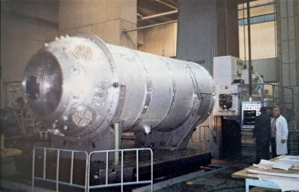
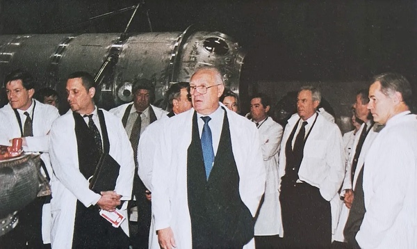 US Congress delegation visits shop 439 at ZEM in 2000. A Science Power Platform pressure vessel visible in the background. Note the presence of the payload bay attachment trunnions. Image: Semyonov 2001 via Nicolas Pillet |
Contraction
One of the early proposed configurations from this period reduced the Science Power Platform to a simple truss with just four solar arrays, berthed to the Pirs docking module, which would be relocated to Zvezda’s zenith port for this purpose.
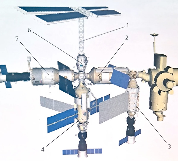 Simplified version of the Russian Orbital Segment: 1 — Science Power Platform (simplified); 2 — Functional Cargo Block; 3 — Multi-Purpose Module; 4 — Universal Docking Module based on FGB-2; 5 — Service Module; 6 — Docking Dompartment. Image: Lopota 2011 via Nicolas Pillet |
While this configuration would have been the easiest to develop, it sacrificed half the power generation capability and transferred all of the heat rejection responsibility to the redesigned Universal Docking Module and the Multi-Purpose Module. The SPP’s gyrodynes, orientation thrusters and science payloads would also need to be transferred elsewhere.
After further studies, in February 2003 a revised proposal which featured the Science Power Module, a reworked version of the SPP, was approved by Russian Space Agency management. By this point, the launch of the Science Power Platform had slipped to January 2007, with the launch carrying the remaining solar arrays scheduled for January 2008. After the redesign, the new Science Power Module was scheduled to launch sometime in 2009.
The Science Power Module would gain an extension to the pressurized compartment with a radial docking port, where Pirs could be redocked. The extendable truss section and the radiator were reduced in size, but the solar arrays retained their size.
A smaller radiator was now part of the new Multi-purpose Laboratory Module, compensating for the reduction on the SPM. The European Robotic Arm was also moved to the MLM, together with roll control thrusters and some payloads. The MLM, built using FGB-2, the structural spare of the Zarya module, has since been given the name Nauka.
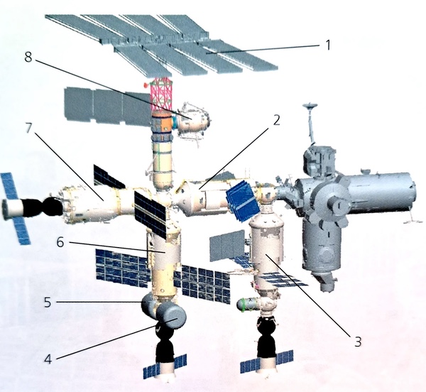 Russian Orbital Segment — 2003 version: 1-Science Power Module; 2 — Functional Cargo Module; 3 — Multi-purpose Laboratory Module; 4 — Small Research Module 2; 5 — Small Research Module 1; 6-Reseach Module; 7 — Service Module; 8 — Docking Compartment. Image: Lopota 2011 via Nicolas Pillet |
This change in direction came but three weeks after Columbia disintegrated on reentry, putting a three year pause on shuttle flights and ISS assembly. A year later, in 2004, the Science Power Module received a minor redesign, with more payloads on the exterior of the pressurized compartment, wider spacing between the solar arrays, and tweaks to the truss structure.
 Science Power Module as proposed by RKK Energia. Images: Zemlya i Vselennaya |
In 2005, the decision was made to retire the Space Shuttle by 2010 and reduce the number of remaining flights to the bare minimum to finish the assembly of the space station.
By joint decision of NASA and the Russian Space Agency, flight 9A.1, which would have carried the Science Power Platform and its successor, the Science Power Module, to the station, was among those cut. This marked the end of the Science Power Platform.
The original module was a vital part of early ISS assembly plans as it provided power to the American modules before the large ITS truss was built, but with the introduction of the Z1 truss, which allowed the American solar arrays to be temporarily attached above the Unity module before the truss was ready, the Science Power Platform lost its strategic importance. It was still the main powerplant for the Russian segment, though, and was designed to provide power and heat rejection capability for nine modules then planned for the ROS.
With more and more Russian modules revised, scaled back, combined with others, or simply cancelled, the SPP made increasingly less sense, especially as its science return was relatively low for the cost of building the 20-meter tower. After the shuttle program started winding down, the Russian side negotiated for a continuation of the power supply deal from the US segment to the Russian modules, which let it get away without its own power module. Still, the arrival of the Nauka laboratory in 2021, along with its solar arrays, noticeably lowered the Russian electricity bills owed to the Americans.
A new Dawn
In June of 2005, the MLM was relocated to Zvezda’s nadir port which, together with the decision to exclusively use the Soyuz for crew rotation from 2009, created a shortage of available docking ports on the Russian segment. At the same time, even with the flight of the Science Power Platform/Module cancelled, NASA remained contracted to deliver a spare elbow joint for the European Robotic Arm and outfitting equipment for the MLM such as the radiator and science airlock.
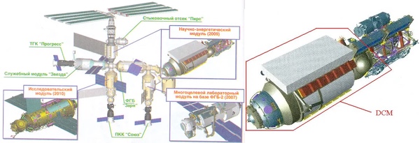
In 2006, RKK Energia started working on how to solve these two problems and came up with a rather elegant solution: the Docking Cargo Module. The DCM would be around six meters long and 2.2 meters in diameter, with one active SSVP-M docking port and one passive SSVP-G to accept visiting Soyuz and Progress spacecraft; the module would be delivered by the Space Shuttle together with the MLM outfitting equipment.
Two designs for the DCM pressure hull were considered. The first—а) in the diagram below—used two forward halves of the Pirs-type docking module welded back-to-back with extra shuttle payload bay trunnions attached. This was essentially a copy of the Mir Docking Module that flew to the ISS’ predecessor on STS-74 in November 1995, but with different docking ports.
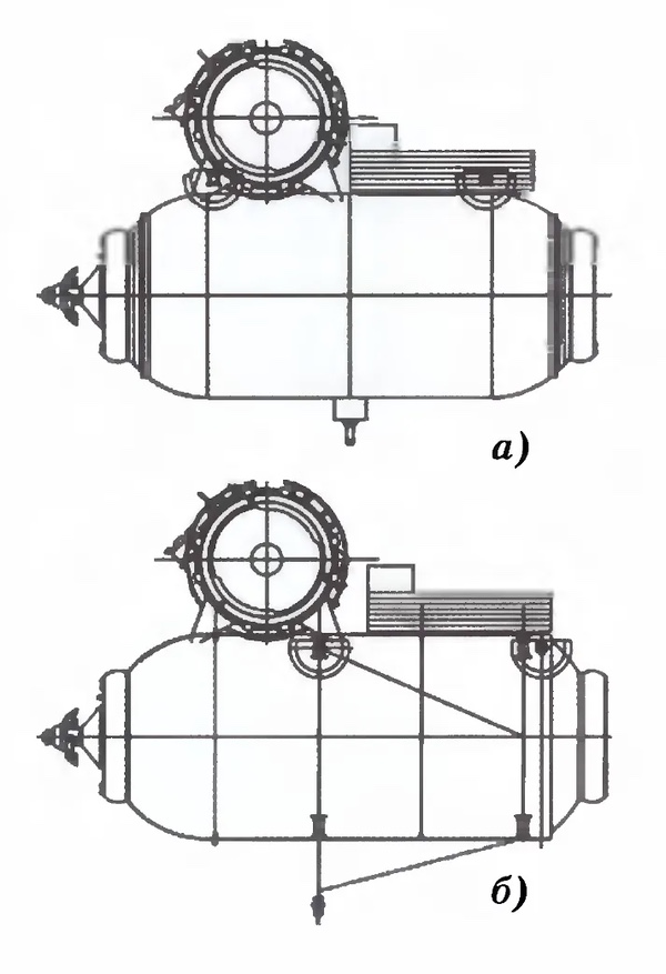 Two DCM variants. Image: Lopota 2011 |
The chosen design—option б) in the diagram—used an asymmetric pressure vessel based on the Science Power Platform pressurized compartment and was proposed by ZEM specialists to make use of the leftover hardware. In May 2007, the module’s creation was approved and its delivery to the station was agreed with NASA. Later that year, it was redesignated as the Mini-Research Module 1 (MRM-1) and given the name Rassvet, meaning Dawn in Russian.
To modify the SPP’s pressure vessel for MRM-1, its aft-most cylindrical section segment and the aft section were removed and a new short aft section based on the Pirs docking module was attached, with extra strengthening and an additional payload bay trunnion. The forward end and the first three cylindrical section segments together with the original payload bay attachment trunnion were retained from the SPP design. Two mothballed Science Power Platform pressurized compartments were used to build Rassvet: the static test article was used for both static and dynamic tests, while the dynamic test article was used build the flight article.
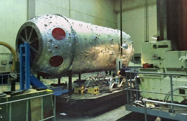 SPP pressure vessel before conversion into the Rassvet pressure vessel. Image: Lopota 2011 via Nicolas Pillet |
One more feature Rassvet inherited from the Science Power Platform was the hand-off maneuver from the Shuttle’s Canadarm to the station’s Canadarm2.
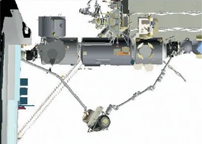 Image: Novosti Kosmonavtiki |
At this point I should probably note that Rassvet is not a copy of the Mir Docking Module. It’s ultimately derived from the same hardware and shares many similarities, but it’s a distinct development that differs in the structural layout. This confusion was probably not helped by the frequent mentions that Rassvet is the “mirror image” of the MDM. This is true insofar as the handedness of equipment installed on the module is flipped because Rassvet flew “feet forward” in the shuttle’s payload bay, with the active port pointing at the aft bulkhead, while the MDM flew with the active port pointing forward, but it does not mean that the design of the module is identical and mirrored.
Epilogue
By December 2009, Rassvet’s assembly was completed and the module was transported to Florida for launch on STS-132 aboard Atlantis.
The mission lifted off on May 14, 2010, and Rassvet was successfully berthed to Zarya’s nadir port four days later, bringing Science Power Platform hardware to the space station almost two decades after the module was conceived.
In the end, the Science Power Platform did not get built as initially designed, but it eventually made it to the ISS in one form or another despite the endless configuration changes. The space station we know in 2026 is made up of hardware first drawn up in the ’80s on the US side too, but the Russian segment hardware seems to have an especially esoteric background with ’80s plans often still veiled in Iron Curtain secrecy all these years later. After all, the Pirs docking module, its twin Poisk, the European Robotic Arm and, of course, the Zvezda Service Module, all formed part of the impressive Mir-2 complex.
Just like Mir-2 itself, the Science Power Platform used to be the future once.
[1] The RKK Energia company history mentions four Zenit launches in the plan agreed in June 1994.
[2] 14.7 or 15.6 tonnes depending on the source.
Thank you to Nicolas Pillet for providing images for this article.
References
- B. Hendrickx, “From Mir-2 to the ISS Russian Segment”, British Interplanetary Society, 2002
- Yu.P. Semyonov (ed.), “S.P. Korolev Rocket and Space Corporation Energia: at the Turn of the Two Centuries”, Moscow, RKK Energia, 2001
- V.A. Lopota (ed.), “Rocket and Space Corporation Energia named after S. P. Korolev in the first decade of the twentieth century. (2001–2011)”, Moscow, RKK Energia, 2011
- V.F. Utkin, “International Space Station and Applications Programme”, Zemlya i Vselennaya, №4, 1995, pp. 3–7
- “‘Mir-2’ Space Station Under Construction”, 12 March 1989, in: JPRS Report Science & Technology USSR: Space, 2 May 1989, p. 53
- S. Leskov, “Blagov on Plans for ‘Mir’ Modules, Mission Durations”, Izvestiya, Moscow, 21 February 1989, p.3
- News Conference Held at Ministry on Space Research Plans to 2005, Moscow World Service, 21 August 1989, in: JPRS Report Science & Technology USSR: Space, 22 November 1989, p. 53
- V.A. Likhachev, A.I. Razov, A.G. Cherniavsky, Yu.D. Kravchenko, S.N. Trusov, “Truss mounting in space by shape memory alloys”, Proc. of 1st Int. Conf. on Shape Memory and Superelastic Technologies, Pacific Grove, California, USA, 1994
- “The Mir-2 long-term orbital station: projects and plans. (VIDEOKOSMOS review)”, Novosti Kosmonavtiki, №25, 1992, pp. 16–19
- “Soviets Preparing Energia Booster/Buran-2 at Baikonur As Follow-On Mir-2 Station Is Canceled in Economic Crisis”, Aviation Week & Space Technology, April 22, 1991, p. 23
- J. Lenorovitz, “Russia to Upgrade Mir 1 Space Station, Prepares for New Orbital Facility”, Aviation Week & Space Technology, May 4, 1992, pp. 84–85
- C. Covault, “Russia Forges Ahead on Mir 2”, Aviation Week & Space Technology, March 15, 1993, pp. 26–27
- J. Lenorovitz, “Russia Redesigns Mir 2; Primary Module Underway”, Aviation Week & Space Technology, August 10, 1992, p. 62
- R. Boumans, C. Heemskerk, “The European Robotic Arm for the International Space Station”, Robotics and Autonomous Systems, Vol. 23, 1998, pp. 17–27, doi.org/10.1016/S0921-8890(97)00054-7
- A. Zak, “Problems in U.S. Space Station Program, Plans for ‘Mir-2’ Proceeding”, Nezavisimaya Gazeta, 6 May 1993, p. 6, in: JPRS Report Science & Technology: Central Eurasia — Space, 28 June 1993, pp. 17–19
- R. Bentall, “Reaching Out on Space: Europe’s Robotic Arm”, On Station, ESA Publications Division, March 2, 2000, p. 10
- J. Rylaarsdam, “International Space Station Traffic Modeling and Simulation”, Master’s Thesis, Air Force Institute of Technology, March 1996, p. 40, after: R. Puckett, “DAC-1: Propellant Resource Assessment TDS 3.1.1–4. Final Report. Transmittal Memo #95–0034–04”, McDonnell Douglas Aerospace Houston Division, March 30, 1995
- J. Smith et al., “Avionics Architecture for the U.S. Segment of the International Space Station Alpha”, AIAA, 1995
- “Assembly Sequence Rev. D” in: “International Space Station Familiarization Manual,” NASA Technical Reports Server (NTRS), July 31 1998, ntrs.nasa.gov/citations/20250005232
- “International Space Station Assembly Sequence (Revision E, June 1999)”, NASA Johnson Space Center, July 1999, IS-1999–06-ISS012JSC, nasa.gov/spacenews/factsheets/pdfs/rev_e.pdf
- “Preliminary ISS Assembly Sequence, Revision B, as of March I, 1996” in: “Space Cooperation: International Space Station. Protocol Between the UNITED STATES OF AMERICA and the RUSSIAN FEDERATION”, June 15, 1996, csps.aerospace.org
- SPP responsibility distribution agreement, Appendix 3, ibid.
- “International Space Station Assembly Sequence: Revision F (August 2000)”, in: “STS-106 Press Kit”, August 29 2000,
- A. Zak, “Science and Power Platform, NEP”, accessed 05.03.2026, available russianspaceweb.com/iss_nep.html
- “International Space Station: Assembly Flight Sequence as of February 2, 2003”, accessed 05.03.2026, spider.seds.org/shuttle/iss_030202.html
- V. Mokhov, “SM sent to Baikonur”, Novosti Kosmonavtiki, №6, 1999, pp. 56–57
- K. Lantratov, “Zvezda: the way to space”, Novosti Kosmonavtiki, №9, 2000, pp. 5–13
- K. Lantratov, “Composition of the ISS Russian Segment”, Novosti Kosmonavtiki, №10, 2001, pp. 22–23
- Yu. Zhuravin, S. Shamsutdinov, “NASA paid for the flights of its astronauts until 2011”, Novosti Kosmonavtiki, №6, 2007, pp. 20–21
Note: we are now moderating comments. There will be a delay in posting comments and no guarantee that all submitted comments will be posted.