
Diamonds and DORIANS: The Soviet Union’s Almaz and the United States’ Manned Orbiting Laboratory military space stations (part 2)MOL and Almaz enter active developmentby Dwayne A. Day and Bart Hendrickx
|
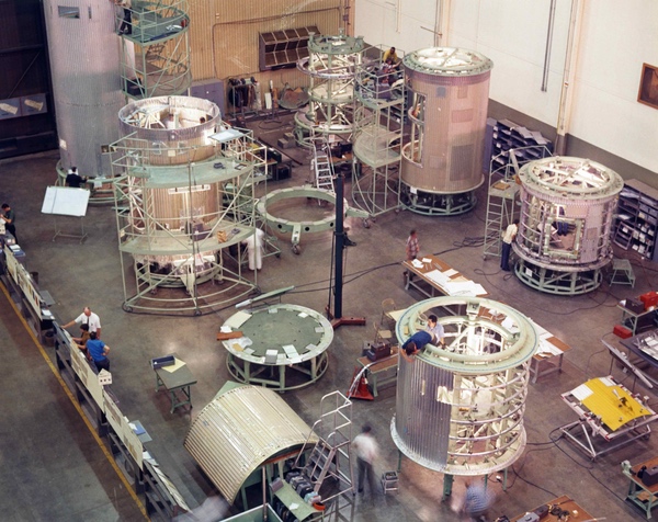 The MOL laboratory was a large vehicle with many components. (credit: NRO) |
MOL consisted of a Gemini spacecraft, a connecting section, a pressurized operations section known as the “laboratory module,” and a large unpressurized segment known as the “mission module” containing the optics. The Gemini was officially known as the Gemini B. It was similar to the NASA Gemini spacecraft with one significant difference: an access hatch located between the astronauts’ seats and passing through the heat shield. This was considered a potential vulnerability. In November 1966, the Air Force launched a Titan III rocket carrying a refurbished Gemini spacecraft equipped with the heat shield hatch. The rocket launched from Florida and the spacecraft flew a suborbital trajectory and splashed down in the Atlantic Ocean, proving that the heat shield worked.
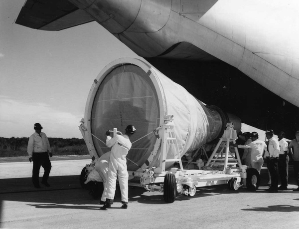 The Gemini B spacecraft had a hatch through the heatshield to enable the astronauts to reach the laboratory module. In November 1966, the Air Force launched a test version of the spacecraft to evaluate the hatch. Here the spacecraft is being unloaded in Florida. (credit: Joe Page II) |
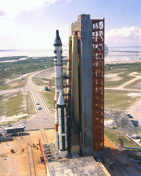
MOL was a heavy payload and required a powerful rocket to reach orbit. The Titan IIIC rocket had added solid rocket motors to the side of a Titan II core stage. It had its first flight in summer 1965. MOL required even more lifting capability, provided by bigger solid rocket motors consisting of seven motor segments. This rocket was designated the Titan IIIM. Testing was not scheduled until 1969.
 The unmanned Gemini test flight was conducted from Florida using a Titan IIIC rocket. Actual MOL launches would take place in California using a more powerful rocket known as the Titan IIIM. (credit: Joe Page II) |
 The Titan IIIC being prepared for flight. The test was successful, proving that the heatshield hatch was safe. (credit: Wikipedia) |
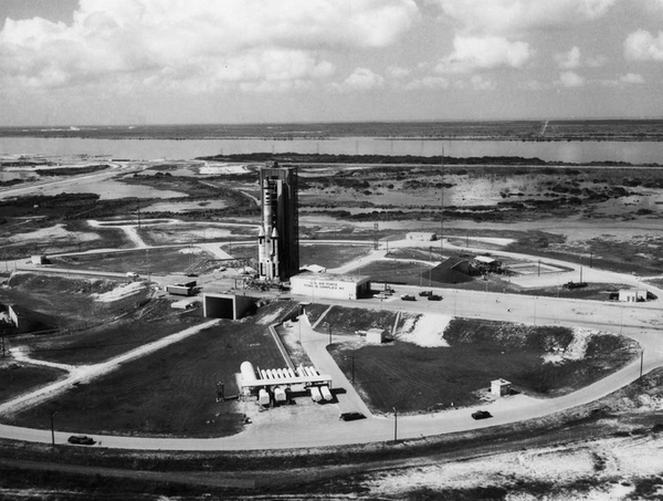
Throughout 1967 and 1968, work progressed on a major construction project at Vandenberg Air Force Base to provide a launch site for the Titan IIIM and support to the payload, including the Gemini spacecraft. Vandenberg had been busy in the late 1950s and through the 1960s for the test-launching of ballistic missiles, and launched operational intelligence satellites on a near-weekly basis, but it had never supported a mission with astronauts. The construction at Space Launch Complex 6 (or “Slick-6”) took place at a southern part of the base on newly-acquired land, and it was one of the largest single construction projects the base had ever seen. After the clearing of land and the establishment of the concrete foundations for the complex, workers began erecting the launch tower and related structures.
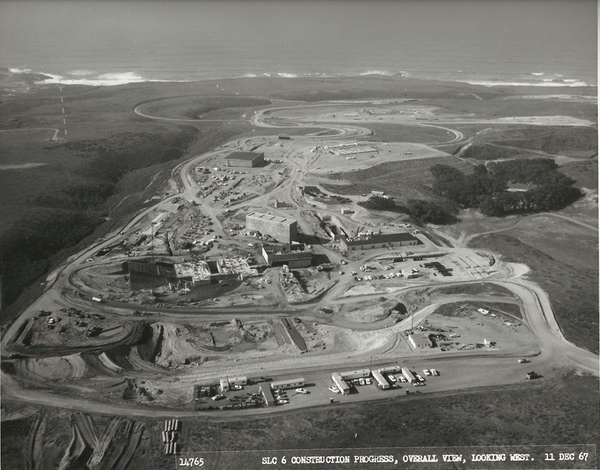 The Space Launch Complex 6 construction site was one of the largest projects at Vandenberg Air Force Base. (credit: Joe Page II) |
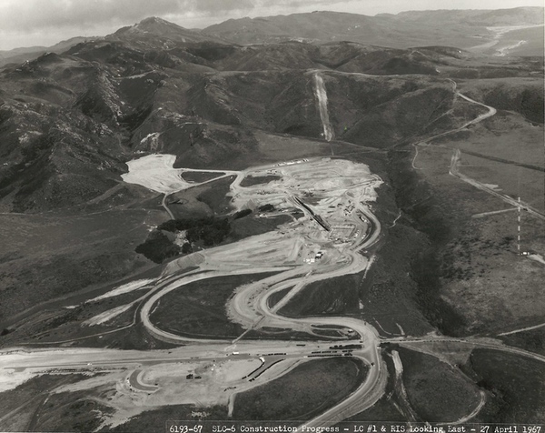 SLC-6 at Vandenberg is nestled between low rising mountains and the Pacific Ocean. The site has recently been turned over to SpaceX and will likely resume launches in 2025. (credit: Joe Page II) |
The Manned Orbiting Laboratory program included a powerful optical system code-named DORIAN, also known as the KH-10 to those who were not cleared to know the specific design features of the hardware. The optical system was mounted in what was known as the “mission module” located behind the “laboratory module.” The mission module was 11 meters (36 feet) long and three meters (ten feet) in diameter. DORIAN was the largest space optics system designed up to that time. It used the same general configuration as the GAMBIT satellite, which had an optical system designed by Kodak. It had a “tracking mirror” on one end—near the middle of the MOL vehicle—which bent the light and sent it to a primary, large focusing mirror at the rear of the spacecraft. The primary mirror then sent the focused image back to a secondary mirror located in front of the tracking mirror. This secondary mirror bent the image up to another mirror that then sent the image into the camera, where the image was projected onto a piece of film.
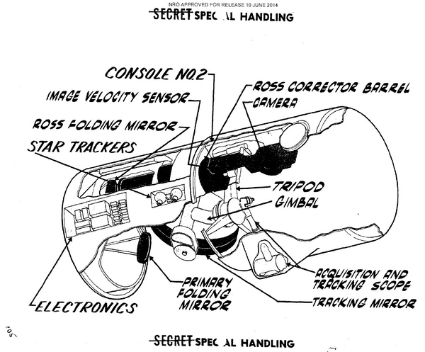 A portion of the DORIAN optical system including the large ”tracking mirror” (also referred to as the “stereo mirror”) which looked down towards the Earth. The astronauts would have been located to the right in this image. (credit: NRO) |
The primary mirror had a diameter of 1.8 meters (72 inches). The focal length remains classified, but based upon declassified drawings that include the dimensions of the mission module, it appears to have been 12.45 meters (490 inches) and f/7, which was the ratio of the aperture to the focal length. (Generally, the lower the f-ratio, the more light reaches the focal point where the film is exposed—like the difference between looking down a short, wide tunnel compared to a long, narrow tunnel, which will naturally be darker.)
The DORIAN system was intended to achieve ten-centimeter (four-inch) ground resolution from orbit. This was referred to as a “very high resolution” or VHR system. (By the 1970s, the term was apparently changed to ultra-high resolution.) The purpose of such high resolution was to provide technical details of certain Soviet weapons systems. For instance, a VHR system could determine the aerodynamic flight surfaces on a Soviet anti-ballistic missile, thus indicating if it was intended to operate in the atmosphere or above it.
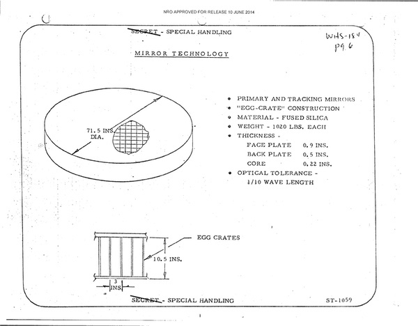 MOL would have used the largest optical system ever flown in space. The mirror was of an advanced lightweight design, and the technology was later adapted to the KH-11 KENNEN and the Hubble Space Telescope. (credit: NRO) |
The big primary reconnaissance camera was augmented with additional optical systems. Robotic spacecraft included cameras that photographed the Earth’s horizon, which provided precise data on how the spacecraft was oriented—for instance, was it pointed straight down or off to one side? They also had stellar cameras that looked up and photographed the stars, providing location data. They often had “terrain” or mapping cameras that took wider field of view images to enable photo-interpreters to look at a big picture image and then compare the reconnaissance photos to know precisely where they were looking.
MOL had some unique requirements. The astronauts needed to see not only what the big optical system was seeing at that moment, but also what potential targets were coming up. MOL therefore had two acquisition optical systems, one per astronaut. The astronauts would work side by side, with their backs towards Earth. Each could peer through their own eyepiece that showed the terrain coming up ahead, as well as through another eyepiece that showed what the KH-10 optical system was looking at at that precise moment. The KH-10 had a primary and secondary eyepiece so that each astronaut could see the powerful view of the ground, good enough to see people walking on a city street.
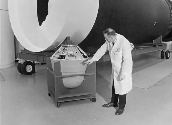
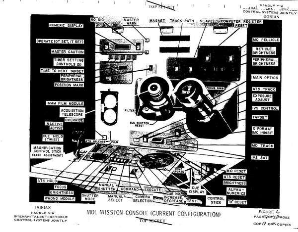 The MOL mission console was connected to a powerful computer—by 1960s standards—that included a pre-loaded target set and allowed the astronauts to prioritize which targets to photograph based upon atmospheric conditions such as clouds as well as intelligence value. For example, photographing a Soviet missile on its launch pad was a high priority. (credit: NRO) |
The astronauts’ job during a photographic pass over a target area was to view the upcoming targets and then prioritize them based upon such factors as visibility (i.e. haze or cloud cover) and interest. They would quickly enter this data into an onboard computer that controlled the pointing of the DORIAN optical system. The computer already had a target database, and the astronauts updated that database in real time. In certain target-rich environments like Moscow, not all targets could be photographed before the spacecraft moved out of view, so this real-time prioritization was valuable. For instance, if while flying over the sprawling Baikonur launch facility in Kazakhstan, the astronauts could decide on which specific launch pads to photograph based upon whether there was a rocket on the pad, or if it was obscured by clouds.
Because MOL was an unusual program with both unclassified and classified elements, many details about it were released while it was under development, although this conveniently helped to obscure and distort what MOL was actually intended to do. For example, the public impression of MOL was that it was a large pressurized compartment and many experiments, rather than a small pressurized compartment and an operational reconnaissance mission.
Based upon the unclassified parts alone, it was clear that MOL was a complex and expensive project. In 1967 the Air Force awarded fixed-price incentive-fee contracts to Douglas Aircraft for $674.7 million and McDonnell for over $180 million. Douglas was responsible for the laboratory module’s unpressurized and pressurized sections and McDonnell for the Gemini B spacecraft. Other sources indicate that McDonnell was supposed to provide four Gemini B spacecraft with options for two or more later. Douglas signed subcontracts for such components as the waste management system, attitude control, and life support. When Douglas and McDonnell merged later that year, the combined company was responsible for a very large Department of Defense space contract.
 The MOL laboratory had the same diameter as the Titan IIIM launch vehicle. Although the pressurized laboratory was small by today's standards, it was the largest human spacecraft under development before Skylab. (credit: NRO) |
Because the astronauts were supposed to live inside MOL for a month-long mission, this drove the requirement to include life support equipment that had not been necessary for Mercury or Gemini. The spacecraft was to be equipped with more food options, as well as a toilet. These were new system developments.
| The public impression of MOL was that it was a large pressurized compartment and many experiments, rather than a small pressurized compartment and an operational reconnaissance mission. |
General Electric also received a contract for $110 million for “experiment integration work,” which included aspects of the highly-classified KH-10 DORIAN optics system. However, Eastman Kodak, which had manufactured both the GAMBIT-1 (KH-7) and GAMBIT-3 (KH-8) camera systems, also was contracted to build the similar but much larger KH-10 system, although the contract amount remains classified. For other robotic reconnaissance programs, the camera system was the largest expense (the KH-9 HEXAGON camera system accounted for over half of the program’s total budget), so the DORIAN system would not have been cheap. MOL, though, had the additional expense of all the systems, including the Gemini spacecraft, needed to support the astronauts. At its peak, Kodak had over 1,000 direct and indirect workers on DORIAN.
One illustration indicates that both General Electric and Eastman Kodak built electronics for controlling the camera system. GE’s work was apparently associated with controlling the large rotating, image reflecting mirror for the DORIAN camera system. This mirror not only tracked the moving ground target but also enabled the camera to take a photograph of the ground from one angle. Then, as the spacecraft traveled over it, the mirror could rotate to a new position and enable the camera to view the ground target from another angle. This stereo photography made it possible to take accurate measurements of objects on the ground.
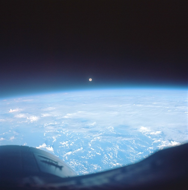 The view from the Gemini 7 spacecraft. Whereas NASA's Gemini missions were used to test equipment, procedures, operations, and people, the Gemini B for MOL was primarily a way for the astronauts to reach and return from space, and the spacecraft would have been unoccupied during the 30-day mission. (credit: NASA) |
Technical intelligence did not have to be timely intelligence. Analysts determining the range of a ballistic missile could make their assessments over time and did not have to do so immediately. But MOL’s 30-day mission was a long time to wait for such expensive photographs, and from the beginning of the program, managers sought methods of returning some of the imagery to Earth before the mission was over.
The DORIAN camera exposed wide-format film that was located inside the pressurized laboratory module. The astronauts could remove the film from the camera. There were three options for returning the imagery to Earth. The first was to store the film inside the Gemini spacecraft in one of three locations established for that purpose. The amount of film that could be carried in the Gemini was limited by mass, but probably also by volume.
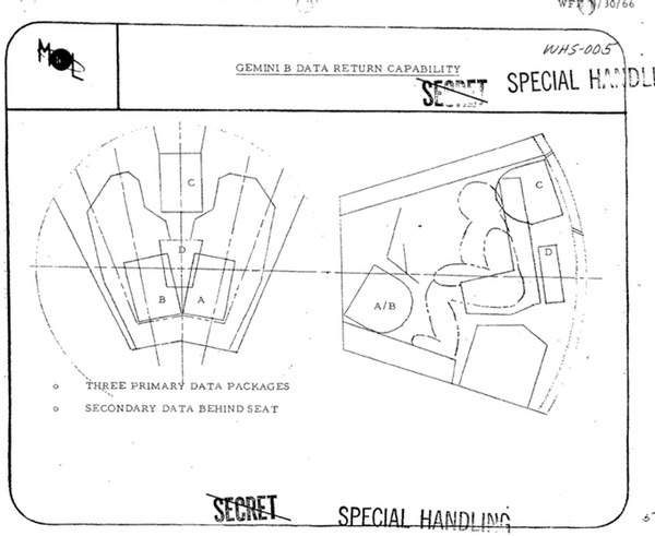 There was only limited room in the Gemini B spacecraft for storing the high-resolution photographs taken during flight. (credit: NRO) |
The second option was to place the film in a reentry vehicle that could then be jettisoned and returned to Earth. This “data return vehicle” was based upon the proven design used for the CORONA and GAMBIT reconnaissance satellites. According to one document, designers considered including up to two of these return vehicles in the MOL. The reentry vehicle could carry 27 kilograms (60 pounds) of film, and the Gemini could return 109 kilograms (240 pounds).
 Another method for returning MOL film to Earth was to pack it inside a reentry vehicle like the one shown here in front of the full-size MOL spacecraft. The Air Force was concerned about putting the reentry vehicle, with its retro rocket and other pyro systems, inside the pressurized spacecraft. (credit: NRO) |
The third option was initially proposed in 1964, but was apparently only included in the baseline MOL vehicle later, possibly by early 1966. That involved developing the film in orbit and scanning it using a laser scanning device that converted the light and dark parts of the film into electrical impulses that could then be transmitted via radio to the ground. By March 1966, Eastman Kodak and General Electric had been contracted to conduct preliminary studies of the performance and the detailed design of a readout system, but program officials concluded that the contractors were not progressing fast enough.
Film-scanning technology had been developed decades earlier for the newspaper industry to enable photographs to be transmitted over telephone lines, and it had been incorporated into the Air Force’s first reconnaissance satellite, Samos. It was later adapted for use by NASA in the Lunar Orbiter program. The available bandwidth limited how many images could be sent to the ground: the MOL astronauts would select only the most important photographs for transmission. The system could be useful for crisis reconnaissance, but its inclusion in the spacecraft was not assured.
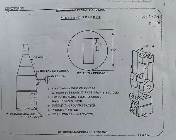 A film readout system was proposed for MOL enabling the astronauts to send images to Earth much more quickly than using the Gemini spacecraft. It was eliminated from the MOL due to the need to cut costs. (credit: NRO) |
Starting around 1965 and continuing through 1966, work had been underway to develop a readout version of the GAMBIT-3 reconnaissance satellite known as FROG. CBS Laboratories was developing a test system to work with the GAMBIT-3 optics. But late in 1966 that work was ordered to be discontinued by February 1967 because the NRO’s Executive Committee concluded that the FROG system could not be afforded and was unnecessary considering the other reconnaissance systems in use by the United States. The NRO Director did make the technology available to the Air Force for possible use in reconnaissance aircraft such as the RF-4C Phantom. Although this never transpired, it was used for a ground-based system for scanning and transmitting aerial reconnaissance photos.
The CBS Laboratories readout system being developed for FROG, along with plans for the ground processing system, became part of the baseline for the MOL, replacing earlier systems being studied by Kodak and General Electric (see “FROG: The Film Read Out GAMBIT program,” The Space Review, February 7, 2022.)
Both the film-readout system and the film-return system were included in the baseline MOL design, although there was increasing uncertainty about whether both were necessary. In November 1966, an internal NRO evaluation concluded that CBS Laboratories had made considerable progress at developing a readout transmission system. More work remained to be done, but the technology was maturing rapidly.
| By February 1967, the MOL program came under major budget pressure. After carefully negotiating contracts with multiple contractors, it became clear that the program would not have enough budget to fund them. |
The DORIAN camera used 23-centimeter-wide film. Each 23-centimeter (9-inch) diameter image on the film had a ground diameter of 2,743 meters (9,000 feet). The readout system was not equipped to transmit an entire frame from the DORIAN camera. Rather, the astronauts would examine the developed film in orbit using a microscope, and then cut out the most important part of the image. This “chip” would then be scanned for transmission to the ground. The system capability was to be up to 160 frame “chips” per day of 5 x 15-centimeter (2 x 6-inch) film-readout, roughly equivalent to 610 by 1,828 meters (2,000 by 6,000 feet) on the ground. A 30-day MOL mission could produce up to 5,364 meters of exposed film, although the amount that would be transmitted to the ground would be relatively small (see “Live, from orbit: the Manned Orbiting Laboratory’s top-secret film-readout system,” The Space Review, September 18, 2023.)
For the surveillance mission the system would provide for target reprogramming, camera performance analysis, and provide time-urgent reconnaissance information. For a technical intelligence mission, it would provide for target reprogramming and camera performance analysis. Compared to the data return vehicle, it could provide daily data return versus only once or twice for the return vehicle, although it is not clear how much crew time this would require.
One of the requirements for the film-readout system was to transmit the maximum resolution of the photography. Because DORIAN was intended to produce ten-centimeter (four-inch) resolution images, the readout system had to be able to transmit ten-centimeter resolution images. This was necessary for evaluating camera performance.
By February 1967, the MOL program came under major budget pressure. After carefully negotiating contracts with multiple contractors, it became clear that the program would not have enough budget to fund them. The MOL program leadership determined that the contract schedules would have to be renegotiated in order to stay within the available budget line. This also put pressure on management to eliminate systems that were not considered essential to the MOL mission such as the readout and data return vehicle systems.
In addition, Eastman Kodak had encountered a problem with the DORIAN system’s fused silica optical components, which due to thermal issues would likely not be capable of achieving the system’s resolution goal for the first two missions. This too may have increased pressure to cancel non-essential equipment.
There were, however, arguments in favor of keeping readout. MOL management was feeling pressure to justify having astronauts on MOL. The readout system was designed to be operated by astronauts, and there was no way that an automatic MOL could select which images to scan and transmit to the ground, or could transmit the massive amount of data in a full-size MOL image.
The MOL program managers increasingly favored the readout system over the data return vehicle. The data return vehicle had a retrorocket and pyrotechnics that posed a risk to the crew, something that became a bigger concern after the January 1967 Apollo 1 fire.
In March 1967, Major General Harry Evans, the deputy director for the MOL program, recommended to the NRO Director that the readout system for MOL be continued and the data recovery capsule be eliminated. Evans argued that the safety and engineering problems of the capsule were serious. He also stated the readout system was superior to the capsule. However, most of his justifications for including the readout system were for engineering testing purposes rather than due to its value as an operational intelligence collection system.
On March 20, Colonel Lee Battle wrote a cable to NRO Director Alexander Flax stating that he had decided to cancel the data recovery vehicle and continue the readout system. However, for reasons that are not completely clear based upon available records, Flax did not approve this decision. According to an April 1967 status report, both the readout system and data return vehicle were deleted from the baseline MOL development program. The mass and volume requirements for both systems were still included in the MOL baseline design in the event that the systems were added back to the vehicle.
According to one source, the readout system was canceled in fall 1967, but it may have had sufficient contract funding to carry it a few months beyond April 1968. A General Electric engineer who worked on the reentry vehicle system indicated that it was always on the verge of cancellation, but did not get canceled before the end of the program. It is possible that it, too, may have continued at a low level of effort using existing funds. Eliminating the reentry vehicle meant that the total film returned would have been limited by the amount that could be carried in the Gemini, even if more could have been carried to orbit.
| Without readout, the mission data was unavailable until the end of the mission, and extending it from 30 days to 45 days increased the delay until people on the ground could see the photographs. |
In October 1968, General Electric began study of a “poor man’s” wide-band readout system. The new study sought to determine if the data could be relayed through an IDCSP or DCS Phase II communications satellite—the former was already in operation and the latter was scheduled for launch in the early 1970s. Using a relay satellite would dramatically increase the time available to transmit the imagery, from only 500 seconds per day using a single ground station to more than 38,000 seconds per day using a satellite in geostationary orbit. More transmission time meant more imagery could be transmitted, although it is unclear how adding this relay capability would have lowered costs.
General Electric provided a report on the capabilities of a readout system by December 1968. The project had often been abbreviated as “R/O” in previous years, and the program decided that in unclassified communications the system would be referred to by the Greek letter “Rho,” although a clever KGB officer might have been able to make the connection.
By May 1969, the plan was to fly four manned MOL vehicles: in July 1972, January and July 1973, and January 1974. If MOL was continued to a Phase II, or Block II configuration, flights could continue on this schedule through January 1976. The Block II MOL could have enhanced capabilities including infrared and multispectral sensors, ultraviolet astronomy, and scene recording and transmission from the tracking scope and the main optics. The mission duration could be extended from the baseline 30 days to a 45-day mission.
One possible upgrade was adding the deleted film-readout capability. The May 1969 report on the Block II vehicle listed several new missions that could be enabled by the availability of readout. These included crisis management, event warning (including missile tests, launch site or downrange activity, satellite launches, nuclear testing, and ABM site activity), targets of opportunity, and request support. As the report noted, without readout, the mission data was unavailable until the end of the mission, and extending it from 30 days to 45 days increased the delay until people on the ground could see the photographs. For the technical intelligence mission this was not a problem, but for event warning and crisis management, the photographs could be useless by the time they reached the ground.
Although DORIAN was the primary intelligence payload for the MOL, in 1965 and 1966 other intelligence payloads were also considered and under development.
By February 1965 there had been a proposal for a communications intelligence (“COMINT”) payload to intercept signals from a Soviet microwave communications system serving both civil and military users. The identity of the target system remains classified, but it apparently consisted of a network of transmitters throughout the Soviet Union. The program manager in the MOL office, Colonel John Copley, determined that intercepting the transmitters’ narrow main beams would be difficult, but that collecting from their sidelobes, which radiated out at much lower power from a transmitter’s sides like the feathers on a peacock, would increase intercept times while a satellite was overhead. In the best case, it could gather up enough information to determine what was being transmitted over the network, at least while the MOL was overhead.
Copley proposed that this signals intelligence collector should be included on MOL. It would use a two-meter (six-foot) diameter parabolic “wrapped rib” antenna that would unfold from the side of the big cylindrical MOL. Unlike an umbrella-type dish, the antenna wrapped flexible ribs and the mesh antenna strung between them around a central spoke, enabling a larger diameter antenna to be packed in a smaller volume.
E-Systems in Garland, Texas, and EDL-Sylvania developed a test system. An Air Force helicopter flew a payload in an intercept pattern through the main beam and sidelobes of a microwave antenna at the E-Systems facility outside Dallas. EDL analysts examined the collected data and made recommendations for a mission. The payload activities were handled within the BYEMAN security control system under a unique management arrangement.
| Simply getting MOL funded was proving to be a major struggle for the program throughout 1967 and 1968. |
Sometime in 1965, with the MOL getting increasingly complicated, MOL program managers decided to eliminate the communications intelligence payload from the spacecraft. Although the details are somewhat murky about exactly when this happened, in November 1965 the SIGINT Working Group of the Committee on Overhead Reconnaissance, which established targets and prioritization requirements for US signals intelligence satellites, determined that the information transferred over the Soviet communications network had “high intelligence value.” In a document, the group declared that a system was required “to obtain sufficient technical data concerning the location, antenna patterns, and modulation of the [deleted] system to permit valid consideration of [a] follow-on collection system.” The group also indicated that this data could be useful for a planned geosynchronous signals intelligence collection system whose name was deleted from the document, but was almost certainly the CANYON communications intelligence satellite then being built by Lockheed and eventually launched in 1968.
With the payload no longer part of the MOL program, National Reconnaissance Office officials soon transferred the project to the program office in Los Angeles that operated the NRO’s growing stable of SIGINT satellites. At some point the payload was named DONKEY. It is unclear when or why the payload received this name, although it clearly had this code-name by early 1966 (see “The wizard war in orbit, part 3,” The Space Review, July 5, 2016, and “Applied witchcraft: American communications intelligence satellites during the 1960s,” October 19, 2020.)
Another system that was under development in 1965 and 1966 was a radar for the Navy that could be mounted on MOL. By fall 1966, responsibility for the sensor was transferred to the NRO, where it was apparently given low priority and deleted from the MOL program. The Navy, unhappy with its treatment by the NRO, sought to develop the sensor on its own, but ran into bureaucratic headwinds. The Navy radar was apparently no longer part of MOL by 1967 (see “Blacker than blue: the US Navy and the Manned Orbiting Laboratory,” The Space Review, October 21, 2019.)
Available records indicate that for the majority of its existence, MOL was intended to carry the DORIAN optical system and no other payloads. Simply getting MOL funded was proving to be a major struggle for the program throughout 1967 and 1968.
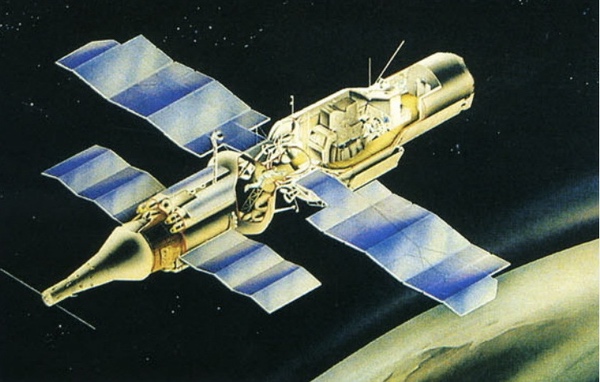
The earliest plans for Almaz envisaged a concept very similar to MOL. The three-man crew would be launched in a return vehicle (VA) attached to the station for missions lasting one to three months, after which the station would be abandoned. Only at a later stage would crews and cargo be delivered to the station in transport vehicles, making it possible to make multiple visits to the station and increase the lifetime to about one year. Advantages of the so-called “autonomous station” were that it would become operational right after reaching orbit instead of having to wait for a crew to arrive. This mission profile also eliminated the risk of losing the station in case the transport ship suffered a launch accident or failed to dock with the station. It should not be forgotten that in the mid-1960s the Soviet Union did not have any experience whatsoever with space rendezvous and docking. The return capsule ensured the safety of the crew throughout the flight. In the event of a launch failure, it could be ejected from the station with a launch escape tower and, in case of an emergency in orbit, it could serve as a rescue vehicle.
The design of the VA return capsule was partially based on that of a piloted circumlunar vehicle (LK-1) that Vladimir Chelomei’s OKB-52 bureau had been working on since August 1964 until that project was transferred to the Korolev bureau about a year later and transformed into L-1 (later officially named Zond.) Aerodynamically, the LK-1 was something of a cross between Gemini and Apollo, and one of Chelomei’s designers later admitted that his team had thoroughly studied the openly available technical literature on those American capsules. Like MOL’s Gemini B, the VA would have had a hatch in its heat shield to allow the crew to transfer to the station. Unlike Gemini B, it was designed to be re-usable for up to ten missions.
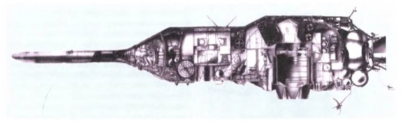 The originally planned version of Almaz with the VA return capsule. (credit: Stolichnaya Entsiklopediya publishers) |
As for the station itself, designers initially looked at the possibility of constructing a long cylinder with a diameter of 4.1 meters, a limit dictated by the fact that the station had to be transported to the Baikonur cosmodrome by rail. However, thеre were fears that this design would make the launch vehicle unstable, and as a result of which it was decided to adopt a tapered design in which the front section of the station had a diameter of just 2.9 meters. This gave it more or less the same shape as the upper composite of the canceled LK-1 circumlunar spacecraft and its Proton launch vehicle, a design that had already undergone extensive wind tunnel tests.
Whereas MOL consisted of an unpressurized section containing the DORIAN telescope and a pressurized section for crew operations, Almaz was essentially one big pressurized structure with a volume of about 90 cubic meters. The main payload (the Agat-1 telescope) was placed vertically inside the 4.1-meter diameter section of the station, looking directly downward to Earth and therefore obviating the need for folding mirrors as in DORIAN. Inside the thinner 2.9-meter section was a workstation to operate the telescope and a living compartment for the crew. At the back of the station was a compartment to install the film return capsules and a small airlock through which the capsules could be ejected from the station.
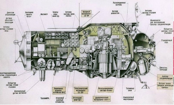 Cut-away drawing of Almaz. (credit: NPO Mashinostroyeniya) |
In the end, the concept of the “autonomous station” was dropped entirely. One of its biggest drawbacks was that the presence of the return capsule imposed major restrictions on the amount of equipment that could be installed inside the station. It also reduced mission duration to just a few weeks. Therefore, it was decided to move directly to stage two.
| Whereas MOL consisted of an unpressurized section containing the DORIAN telescope and a pressurized section for crew operations, Almaz was essentially one big pressurized structure with a volume of about 90 cubic meters. |
The first transport ship that was considered for Almaz was a modified version of the 7K-VI/Zvezda vehicle that was being designed by Branch number 3 of Sergei Korolev’s OKB-1 design bureau in Kuibyshev (see part 1.) This was apparently because it had already gained experience with designing a docking mechanism that would allow the crew to move to another vehicle internally as part of the original Soyuz-R proposal that preceded 7K-VI. The “standard” Soyuz then being developed by OKB-1 itself had a crude docking mechanism that made it necessary for cosmonauts to move to a docked vehicle by extravehicular activity, as demonstrated during the Soyuz-4/5 mission in 1969.
Branch number 3 considered to split the crew/cargo transport functions by designing both a crewed and an unmanned cargo version of 7K-VI. However, when the design was evaluated in the spring of 1967, it was concluded that the cargo vehicles would have to be launched about every three weeks to ensure the proper functioning of the station. Also, by this time it had been decided that Almaz would be equipped with film return capsules, which regularly had to be replenished. These capsules were too big to be transferred to the station through the 7K-VI hatch. Consequently, OKB-52 proposed a much larger and much more capable transport vehicle that would double as a crew ferry and cargo truck. Launched by the Proton rocket, it would be about the same size as the station itself and became known as the Transport Supply Ship (TKS).
Serving as the basis for the TKS design was the original, “autonomous” version of Almaz. The station’s hull was shortened and attached to the VA return vehicle. The redesigned hull, which acted as the cargo section, was called the Functional Cargo Block (FGB). Attached to the aft part of the FGB was a conical section with an active docking mechanism. This conical section had the same shape as the bottom section of the Proton rocket’s third stage fuel tank. Since there was not enough room to install the engine system and propellant tanks in the aft of the vehicle (as on Almaz itself), they were placed on the outer hull. Circular fuel tanks would not have fit inside the payload shroud, so they were replaced by eight long, tube-shaped propellant tanks on the circumference of the vehicle. The vehicle’s engines could be used to boost the altitude of the station’s orbit.
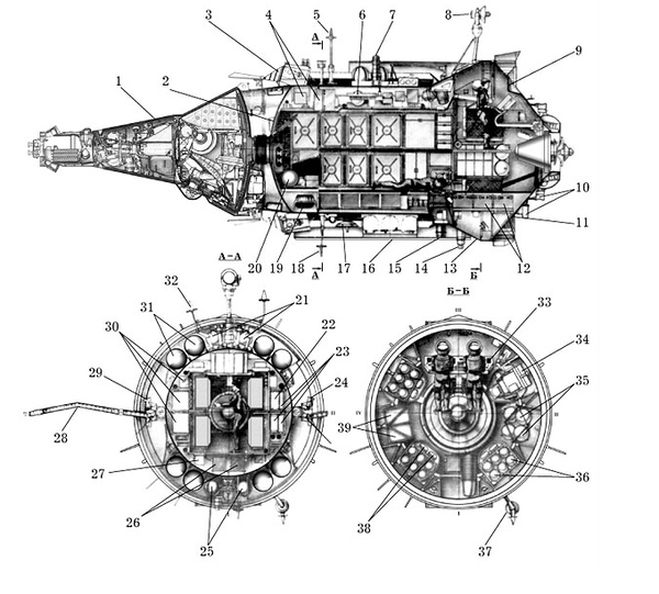 Cut-away drawing of TKS. (credit: NPO Mashinostroyeniya) |
 Artist’s conception of TKS docked to Almaz. |
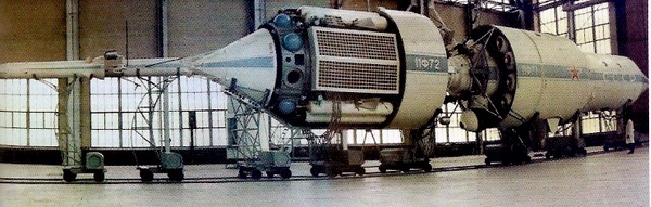 Docked test models of TKS and Almaz. (credit: NPO Mashinostroyeniya) |
Since TKS was not expected to be ready in time for the first Almaz missions, a decision was made in July 1967 to use Soyuz as an interim transport vehicle. This would be a version derived from OKB-1’s traditional Soyuz vehicle, with the descent capsule in the middle. By the time Almaz flew in the 1970s, the docking mechanism of Soyuz had also been redesigned to enable the crew to transfer to the station internally.
The key goal of Almaz was to obtain detailed imagery in the visible part of the spectrum. The requirement laid out in the July 1966 government decree on Almaz was for the station to return imagery with a ground resolution of 50 centimeters to 1 meter. This was to be achieved with an optical system named Agat (“agate”, a type of quartz), which used a 1.5-meter mirror and had a focal length of ten meters. According to the 2019 Almaz history Ogranka Almazov, the resolution of Agat could actually have been as good as 35 centimeters. However, the design proved to be too complex: among other things, it would have required the telescope to be launched in a folded state and be fully extended through an opening in the hull after reaching orbit. Chelomei’s team reverted to a simpler telescope with an 88-centimeter mirror and a focal length of 6.375 meters. It would use optics that had already been developed for unmanned television reconnaissance satellites that OKB-52 had begun working on in 1963 (see ”Soviet television reconnaissance satellites”, The Space Review, September 5, 2023.) Unlike the Zenit film-return satellites, these satellites would have been able to send back imagery in near real time, but they were canceled later in the 1960s. The simpler camera, still weighing 1.2 tons, was called Agat-1, with the hope being that the originally planned camera would later still fly under the name Agat-2. The prime contractor for Agat-1 was the Krasnogorsk Mechanical Plant (KMZ).
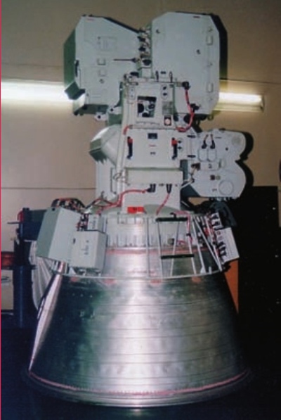 The Agat-1 camera. (credit: NPO Mashinostroyeniya) |
Mounted on top of the telescope were three big film cassettes: two identical ones containing 500 meters of 42-centimeter-wide film and another one containing 500 meters of 53- centimeter film. Several types of fine-grained photographic film, both black-and-white and multispectral, were used, offering a quality not achieved by spy satellites. The exposed 42-centimeter film was sent back to Earth in return capsules for development on the ground and the 53-centimeter film was developed on board the station itself, after which the cosmonauts relayed the more strategically important images to the ground via radio channels.
| Agat-1 was still no match for MOL’s DORIAN telescope with its 1.8-meter mirror and maximum resolution of ten centimeters. |
The cosmonauts played an important role in operating Agat-1. Using two forward-looking optical systems—one wide-angle panoramic system (POU) with a resolution of 30 meters and a narrow-field optical visor (OD-5) with a resolution of one meter—they could look at regions that were well ahead of the station’s flight path, briefly freeze the image with the help of a scanning mirror in the optical visor, and aim the Agat-1 camera at targets of interest. The cosmonauts also recorded their visual impressions of the observed targets on audio tape and communicated them to the ground via secure radio channels. Like MOL’s DORIAN telescope, Agat-1 was to work in conjunction with a topographic camera (SA-34R) and a stellar camera (SA-33R) that took images of the ground and star fields to help determine the exact coordinates of the observed areas.
The authors of the 2019 Almaz history give the maximum resolution of the imagery returned to Earth as one meter and that of the imagery transmitted to the ground as 1.5 meters. Interestingly, they refer to research done by Swedish space historian Sven Grahn, who used optical formulae to calculate that the maximum ground resolution of Agat-1 may have been as good as 43 centimeters. This indicates that they had no access to (probably still classified) data on the actual resolution achieved by the Agat-1 system and that the given values came from documents describing the telescope’s expected performance.
At any rate, Agat-1 was still no match for MOL’s DORIAN telescope with its 1.8-meter mirror and maximum resolution of ten centimeters. That kind of resolution was mainly needed to provide detailed technical intelligence on Soviet weapons systems. Almaz had much broader strategic and tactical objectives, many of which could also be achieved with lower resolution. As can be seen in a declassified diagram published in the 2019 Almaz history, these were:
Like MOL’s Gemini B vehicle, the transportation systems envisaged for Almaz (the modified 7K-VI, TKS and the standard Soyuz) had a very limited ability to return exposed film back to Earth together with the crew. This is why the bulk of the imagery would have to be delivered to Earth in dedicated film return capsules or relayed to the ground via film readout systems. In contrast to MOL, these were not seen as competitive proposals, but complementary data return techniques.
The data return capsules were officially called “Special Information Capsules” (KSI). Shaped like a thimble, they consisted of a pressurized compartment, a small solid-fuel deorbit engine, and a parachute system. Fully loaded, they weighed roughly 400 kilograms, about 120 kilograms of which was cargo. Most of this was exposed film from the Agat-1 camera, wound in two spools, each of which could carry 500 meters of 42-centimeter-wide film. There was also room for exposed film from the topographic and stellar camera as well as audio tapes recorded by the crew.
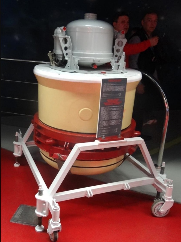 Almaz film return capsule (without heat shield) on display in Moscow. Source |
As noted above, the need to regularly send new film return capsules to the Almaz stations was one of the factors that drove the design of the big TKS transport vehicles. Each TKS was supposed to carry eight return capsules to the station along with its three-man crew. All of these were to be sent back to Earth with exposed film during the three-month missions that were expected to be flown. The capsules could be ejected from the station’s airlock either by a command from the crew or automatically from the ground. In order to ensure that they didn’t accidentally land on foreign territory, they were equipped with a self-destruct system that would be activated in case something went wrong during the return to Earth.
While the film returned by the KSI capsules would need at least several days to reach photo interpreters, the most critical imagery could be returned to Earth almost instantaneously using a film scanning system. Like the United States, the Soviet Union had already tested an experimental film readout system on some of its early automated spy satellites in the early 1960s, but the resolution was so low that it was abandoned. The country continued to rely solely on film-return spy satellites until 1982, when it finally launched its first digital reconnaissance satellite, six years after the US pioneered that technology with its KENNEN satellites.
The film readout system was named Pechora (after a Russian river) and operated very much like the one planned for MOL. The cosmonauts would first cut 1- to 50-meter-long pieces from the exposed 53-centimeter-wide film and then place them in an automatic film development system. After the film was developed, they would inspect it using an optical system named Svet (“light”) and mark the images that were worth transmitting to Earth. These were scanned and turned into television signals that were subsequently beamed to the ground.
Whereas SIGINT and radar payloads were only short-lived proposals for MOL, Almaz was advertised from the outset as a space station that would observe targets in various parts of the electromagnetic spectrum. Radar, infrared, and signals intelligence payloads were to complement the data provided by the Agat-1 telescope.
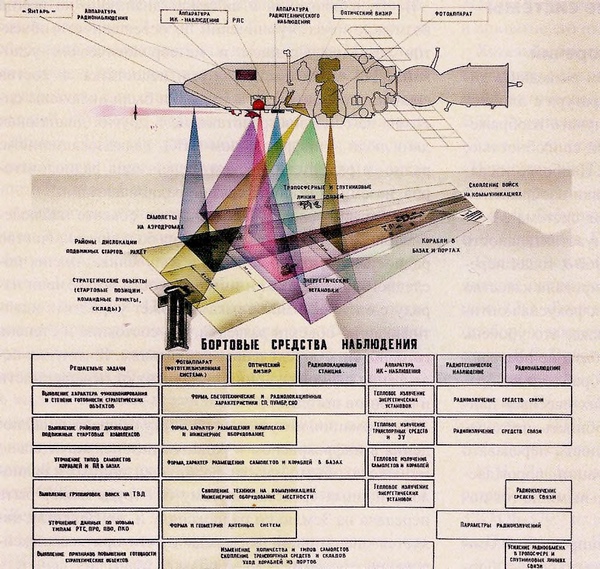 A diagram from the 2019 Almaz history shows the tasks to be carried out by Almaz payloads in various parts of the electromagnetic spectrum. Protruding from the nose of Almaz is the Mech-A radar. (credit: NPO Mashinostroyeniya) |
In the early years of the Space Age, space-based radar observations were of higher priority in the Soviet Union than they were in the United States. After a short test flight of the experimental QUILL satellite in late 1964, the United States military abandoned radar satellites until the 1980s. Several years before the launch of QUILL, Chelomei’s OKB-52 design bureau had begun working on a nuclear-powered radar satellite called US-A (“active controllable satellite”) that saw its first test flights in 1965 and would continue to fly until 1988. The US-A satellites were designed to locate the position of enemy surface vessels in order to provide targeting data for OKB-52’s anti-ship cruise missiles.
| Almaz was supposed to carry an impressive array of equipment to defend itself against anti-satellite attacks. |
The development of the US-A radar system (named Chaika or “seagull”) was in the hands of the Moscow Research Institute of Instrument Building (MNIIP, now the Vega Concern), which was assigned to build a new radar system for Almaz based on the experience it had gained with Chaika. The choice fell on an S-band radar operating at a wavelength of around ten centimeters. This was because S-band radar signals are less susceptible to adverse weather conditions and have a better ability to penetrate foliage and soil than X-band signals. Designated Mech-A (“sword”), the radar consisted of a single 15x1.5-meter antenna attached to the station’s outer hull. The radar images were to be recorded on photographic film and delivered to Earth aboard the film return capsules.
Mech-A was a side-looking radar that could see an area of 100 kilometers either to the left or right of the station’s ground track. This meant that it could not be used to simultaneously observe the same objects photographed by Agat-1, but it was still seen as a vital tool to obtain time-critical imagery of regions that were covered in cloud. Unlike Chaika, which was aimed at ocean reconnaissance, it would be used to fulfill the same tasks as Agat-1, except for the location of mobile launch systems and intelligence of radar systems. Mech-A did suffer from one handicap that still made space-based radar relatively unattractive at the time, namely its low resolution of between 20 and 30 meters.
The infrared payload, called Volga, was provided by the State Institute of Applied Optics (GIPO). It consisted of a 50-centimeter fixed mirror and a rotatable mirror capable of scanning a swath of about 30 kilometers. It operated in the mid-wavelength infrared between 3.2 and 5.2 microns and had a resolution of about 100 meters. Volga was designed to detect the infrared signature of aircraft, ships, and other transportation systems as well as what are defined as “energy installations”. The only mission it could not be used for was intelligence of radar systems. The infrared images would be sent back to Earth in the film return capsules.
Also planned for Almaz was a signals intelligence payload named Start that was to be delivered by NII Vektor. Judging from the declassified diagram in the Almaz book, it would have been used both for electronic and communications intelligence. Aside from pinpointing the location of radars and collecting data on their technical features, the payload would also be able to pick up voice traffic. An increase in such traffic could, for instance, point to preparations for an imminent enemy attack.
In addition to all this, Almaz was supposed to carry an impressive array of equipment to defend itself against anti-satellite attacks (see “Self-defense in space: protecting Russian spacecraft from ASAT attacks”, The Space Review, July 16, 2018.) This included an infrared detector to spot launches of ASAT interceptors, a periscope and a radar to scan the station’s surroundings for incoming interceptors, a radar jamming device, decoys and a rapid-fire cannon (originally developed for 7K-VI), which later was to be replaced by space-to-space missiles with a range of 100 kilometers.
Some of these payloads were scheduled to be introduced only in a later phase of the Almaz project and not all of them would make it into space.
Note: we are using a new commenting system, which may require you to create a new account.
